Description
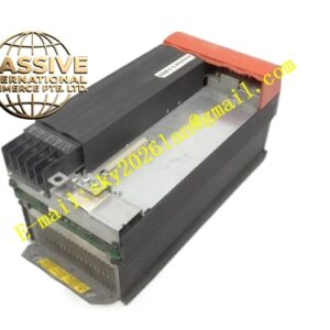
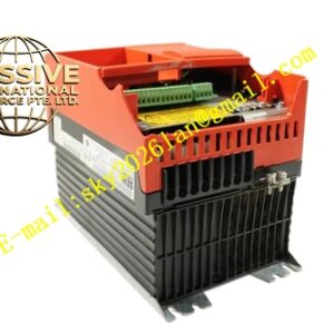
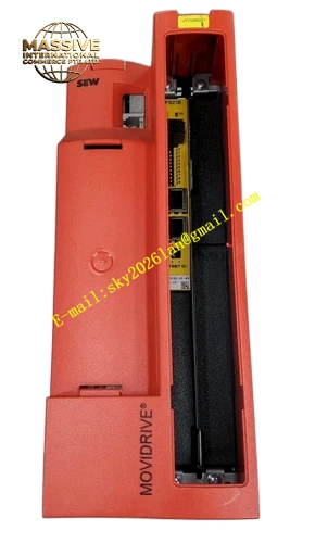
SEW MDX61B0075-5A3-4-00
Technical Specifications:
- Brand: SEW-EURODRIVE
- Series: MOVIDRIVE MDX60B/61B
- Rated Output Power: 7.5 kW
- Rated Output Current: 14.4 A
- Apparent Power: 11.2 kVA
- Input Voltage: 3-phase AC 380–500V, 50/60 Hz
- Voltage Tolerance: ±15%
- Output Frequency Range: 0–550 Hz
- Protection Rating: IP20 (standard), IP65 (optional)
- Operating Temperature: -30°C to +80°C (forced cooling extends to +70°C continuous)
Functional Features:
- Field-Oriented Control (FOC): Achieves 30%–50% energy savings in variable torque applications
- Built-in Braking Chopper: Supports four-quadrant operation for motor forward/reverse and rapid braking
- S-Curve Ramp Function: Reduces mechanical shock during acceleration and deceleration
- PID Regulation: Enables precise closed-loop control of flow, temperature, or pressure
- Multi-Motor Synchronization: Speed accuracy of ±0.05% across synchronized drive groups
- 12 Integrated Protection Functions: Overcurrent, overvoltage, undervoltage, overheating, ground fault detection with response time under 100 ms
Application Scenarios:
- Conveyor belt systems in manufacturing and logistics
- Hoisting and crane equipment
- Pump and fan energy-saving applications
- Glass factory tempering processes
- Chemical process pump speed control
- Pharmaceutical reactor agitation
Performance Parameters:
- Overload Capacity: 150% rated current for 60 seconds, 200% immediate shutdown
- Dynamic Response Time: <100 ms (vector control mode)
- Speed Accuracy: ±1% (open-loop vector control)
- MTBF: 100,000 hours
- Standby Power Consumption: Reduced to 0.008% of rated power in sleep mode
Material Composition:
- Industrial-grade IGBT power modules
- Modular power unit, control board, and cooling fan (independently replaceable)
- Aluminum heat sink with forced air cooling
- Anti-corrosion coating option for harsh environments
Structural Features:
- Modular unit design for simplified maintenance
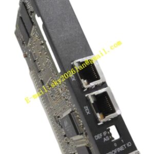
- Expansion slots for optional interface cards
- Integrated braking chopper circuit
- LED status and fault indicators
- Standard terminal block connections for power, motor, and control signals
Working Principle:
The inverter converts AC input to DC through a three-phase rectifier, stores energy in the DC bus capacitors, and synthesizes a variable-frequency PWM output through IGBT switching. The FOC algorithm uses coordinate transformation to independently regulate the motor’s magnetic flux and electromagnetic torque, achieving high-efficiency operation across the full speed range. The PID controller processes analog or digital feedback signals to maintain precise process variable regulation.
Installation Requirements:
- Install in a dry, ventilated environment free of corrosive gases
- Ensure adequate ventilation around the heat sink
- Use shielded motor and power cables with proper grounding
- Connect braking resistor when dynamic braking is required
- Verify input voltage stability within ±15% tolerance
- Anti-corrosion coating recommended for chemical and paper industry installations
Usage Notes:
- Perform motor initialization when connecting a new motor
- Configure PID parameters according to the specific process requirements
- Monitor fault codes through the integrated display or MOVITOOLS software
- The modular design allows independent replacement of power unit, control board, or fan without full unit replacement
- Verify braking resistor impedance matches the drive specifications