Description
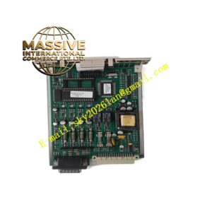
SHINKAWA VM-5G0-2
Technical Specifications: Model: VM-5G0-2 Input: Pulse signal from magnetic pickup or tachometer probe Measurement function: Rotating speed, zero speed detection Output: 4-20mA analog output, multi-level relay alarm contacts Power supply: 24VDC Operating temperature: 0℃ to +60℃ Storage temperature: -20℃ to +70℃ Relative humidity: 5% to 95%, non-condensing Mounting: Plug-in card for VM-5 series rack
Functional Features: Shaft rotating speed measurement from tachometer pulse input. Zero speed detection function for machine turning gear state. Configurable overspeed and underspeed alarm thresholds. 4-20mA analog output proportional to rotating speed. Tachometer probe cable break fault diagnosis. Front panel digital display of real-time shaft speed value. LED indicators for speed status and alarm conditions. Selectable alarm latch and automatic reset function.
Application Scenarios: Steam turbine overspeed pre-warning supervision, gas turbine speed monitoring, compressor zero speed interlock protection, generator turning gear state detection, turbomachinery start-up sequence control, power plant TSI system speed measurement.
Performance Parameters: High accuracy speed calculation from pulse input. Wide measuring range for low speed zero speed and high overspeed condition. Fast response to sudden shaft speed variation. Stable measurement with pulse signal noise filtering.
Material Composition: FR4 printed circuit board. Pulse signal conditioning and shaping circuit. Microprocessor for speed calculation and threshold judgment. Relay components for alarm contact output. Flame retardant metal front panel with digital display. Gold plated backplane connector for rack bus.
Structural Features: VM5 rack plug-in module design. Front panel with digital speed display and status LED indicators. Front screw terminal blocks for tachometer probe wiring and signal output. Internal circuit for pulse signal isolation and noise filtering. Metal front panel for EMC shielding.
Working Principle: Tachometer probe generates pulse signal proportional to shaft rotating speed. The module receives pulse signal, shapes and filters the waveform. Microprocessor counts pulse frequency and converts frequency value to rotating speed. Measured speed value compares with preset overspeed, underspeed and zero speed thresholds. When speed crosses threshold, corresponding relay contact changes state and triggers alarm. Analog 4-20mA signal transmits real-time speed value to DCS system. Diagnostic circuit monitors pulse signal continuity and reports probe wiring fault.
Installation Requirements: Insert module into VM-5 rack assigned slot. Use shielded cable for tachometer probe wiring. Install rack in IP20 rated cabinet. Complete protective earth connection for rack chassis. Set pulse number per revolution parameter matching the gear tooth quantity.
Usage Notes: Configure tooth number parameter during commissioning. Verify pulse signal amplitude from tachometer probe. Test zero speed and overspeed alarm function before machine operation. Cut rack power supply before removing module. Inspect probe mounting gap and cable connection regularly.