Description
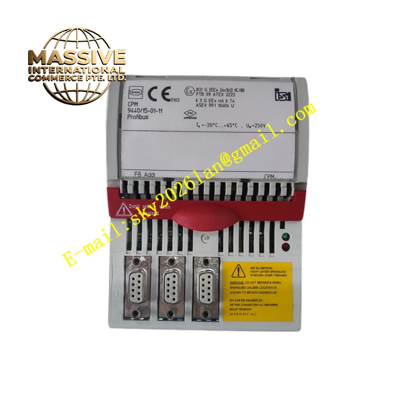
Stahl 944015-01-11
Technical Specifications Intrinsic safety explosion-proof certification; galvanic isolation between safe and hazardous zones; limit of voltage and current output to field side; support for analog 4-20mA signals; DIN rail mounting; wide ambient operating temperature.
Functional Features Restricts the maximum energy delivered to field intrinsically safe devices in hazardous areas. Provides electrical isolation between control room circuits and field hazardous area circuits. Transmits analog measurement signals from field transmitters to control system I/O modules. Detects abnormal circuit conditions and protects against energy overflow.
Application Scenarios Oil refineries, chemical plants, gas storage facilities and other zones with flammable gas or vapor classified as hazardous explosive locations.
Performance Parameters Precise energy limiting characteristic; high isolation voltage between safe and hazardous sides; low signal insertion loss; stable signal transmission in long-term continuous operation.
Material Composition Housing is flame-retardant and explosion-proof thermoplastic; internal isolation transformer and protection components are explosion-proof rated; terminal screws are nickel-plated steel; circuit board is FR-4 flame-retardant PCB.
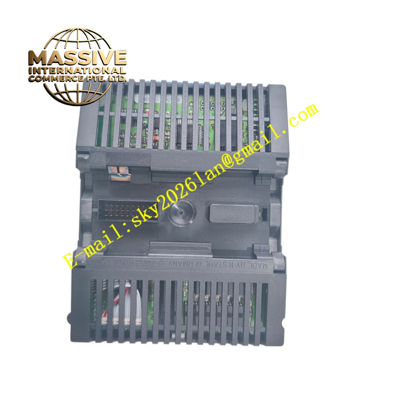
Structural Characteristics Thin rectangular DIN rail mounted housing; two groups of isolated terminal areas separately for safe zone wiring and hazardous field wiring; front panel with status indication marks; rear integrated DIN rail fixing buckle.
Working Principle The barrier uses voltage and current limiting circuits to cap the maximum electrical energy that can reach the field hazardous side. The isolation component separates the ground reference of the control room and field circuits. Analog measurement signals pass through the isolation circuit while the energy limit function stays active at all times.
Installation Requirements Install the barrier inside a non-hazardous control cabinet. Separate the wiring terminals of hazardous side and safe side completely. Follow explosion-proof standard grounding requirements. Verify parameter matching with field intrinsically safe instruments before putting into service.
Precautions for Use Strictly abide by the temperature and gas group limits specified by the explosion-proof certificate. Do not modify internal circuit components of the barrier. Replace the whole unit immediately when the barrier suffers overvoltage damage.