Description
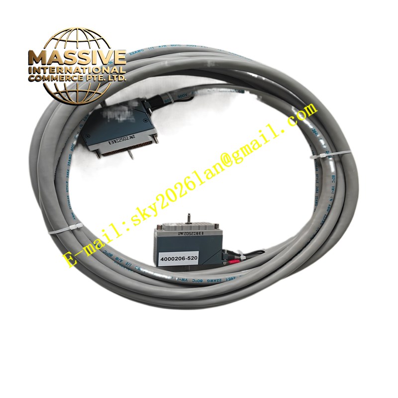
Triconex 4000206-520
Technical Specifications Triple modular redundant circuit design; safety discrete output channels; backplane communication with Triconex main chassis; internal hardware voting logic; online fault diagnosis; certified for high safety integrity level applications.
Functional Features Receives safety command data from the Triconex main processor over the system backplane. Executes hardware voting among three redundant signal paths to determine final output state. Drives field safety actuators to execute shutdown actions when safety trip commands are received. Performs continuous self-test of each redundant channel and reports channel faults to the system diagnostic manager. Supports hot spare replacement while the system remains online.
Application Scenarios Petrochemical emergency shutdown systems, power plant boiler protection, refinery safety instrumented systems and other critical process safety applications requiring high reliability.
Performance Parameters High integrity fault tolerance; consistent output state after three-path voting; fast safety trip response; continuous online diagnosis of each redundant circuit.
Material Composition Circuit board substrate is high-reliability FR-4 multilayer PCB; redundant logic chips and output drive components are industrial safety grade; backplane connector contacts are gold-plated; module front panel is coated metal alloy.
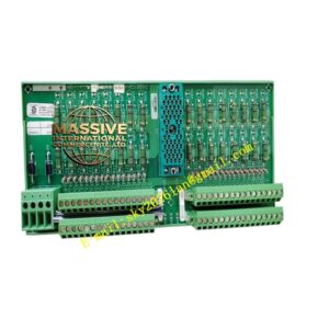
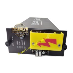
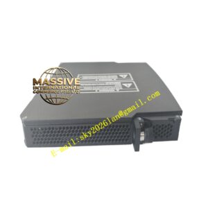
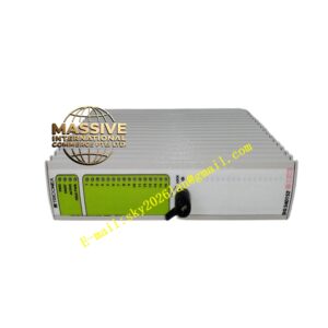
Structural Characteristics Plug-in card structure matching Triconex standard safety rack; front panel with multi-color status LEDs for each redundant channel; rear gold finger connector connected to the triple redundant backplane; front panel locking levers for fixing the module in the chassis.
Working Principle The three independent processor paths of the Triconex system send safety output commands to this module. Three redundant circuits inside the module receive the commands separately and perform hardware voting. The module only executes the output action approved by the majority of redundant channels. Every circuit path runs continuous self-check, and any faulty channel is isolated without affecting the overall safety output.
Installation Requirements Follow Triconex safety system maintenance procedures. Insert the module into the designated slot of the Triconex chassis and lock the front levers. Complete field actuator wiring according to safety loop diagrams. Perform channel and voting logic verification after module replacement.
Precautions for Use Only trained safety instrument system engineers can perform maintenance work. Do not bypass the voting logic or modify internal hardware circuits. Conduct periodic proof tests of the safety output loop as required by safety standards.