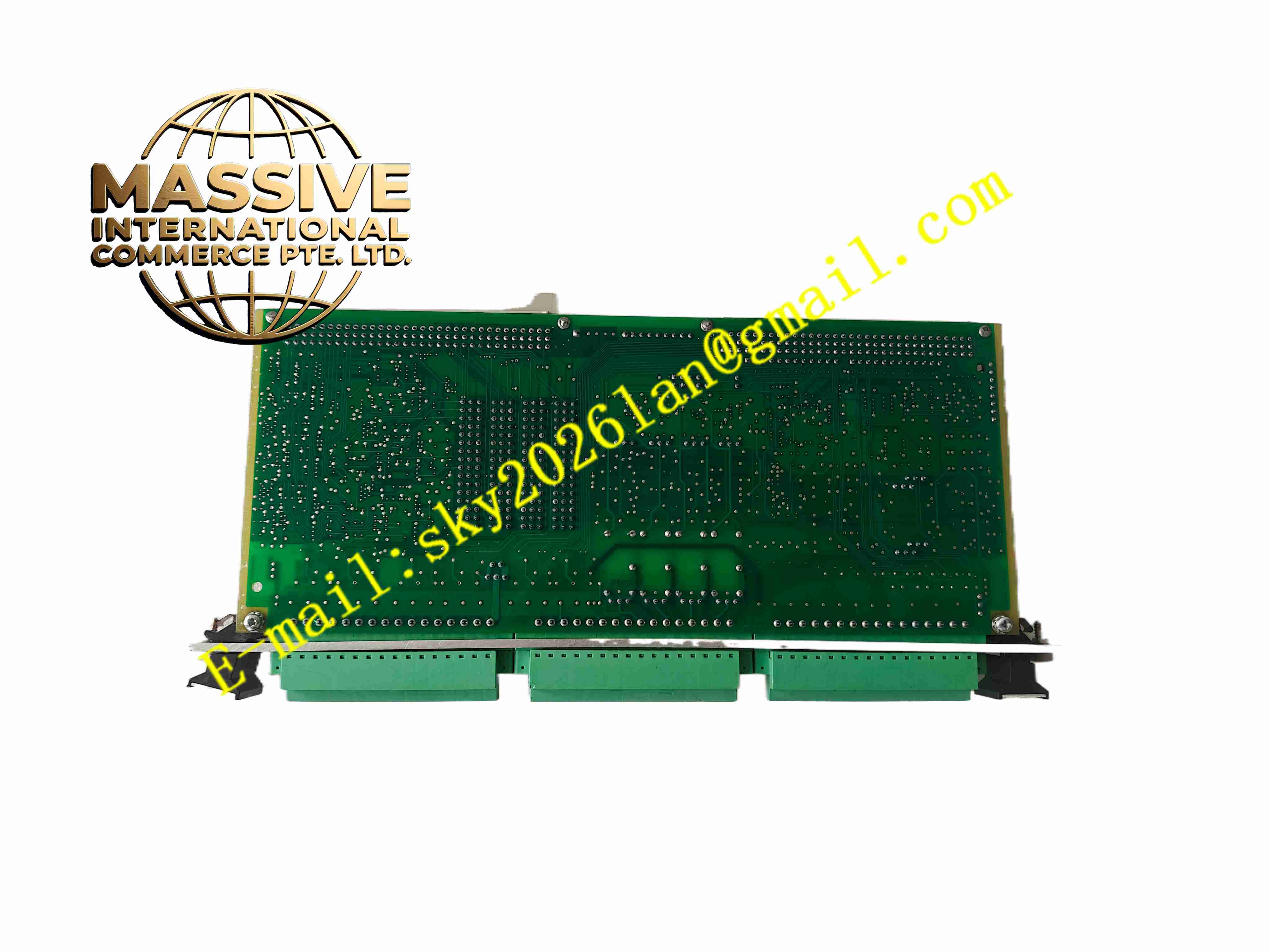
Description
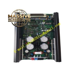
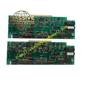
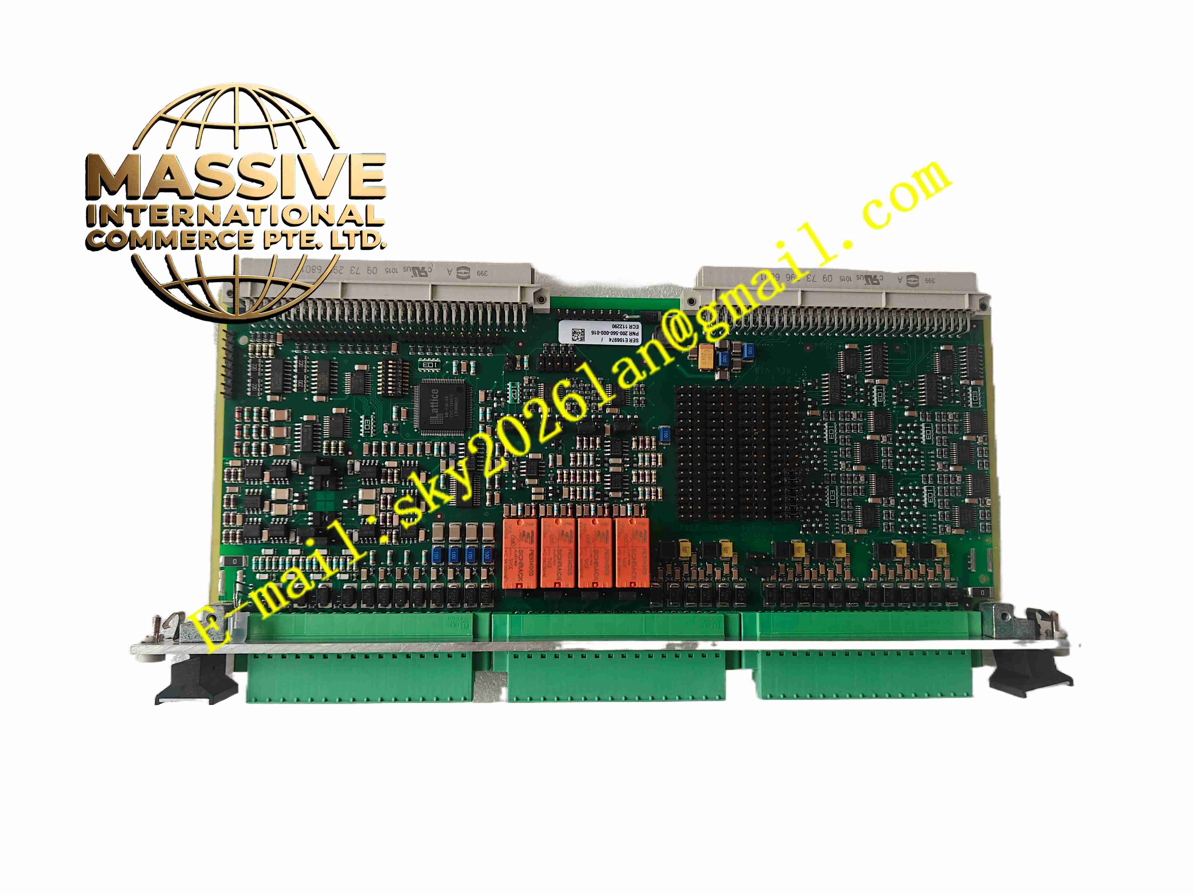
Vibro-Meter IOC4T 200-560-000-016
Technical Specifications
- Board type: Analog/digital output terminal transfer board
- Channels: Multi-channel buffered output and relay output
- Signal type: Vibration displacement buffered signal, bearing temperature signal, alarm relay contacts
- Relay contact rating: AC250 V 3 A / DC30 V 5 A
- Output signal: 4 to 20 mA or voltage buffered signal
- Supply: Rack backplane DC24V
- Temperature: -20 °C to +70 °C
- Storage: -40 °C to +85 °C
- Humidity: 5 % to 95 %, non-condensing
- Protection: IP20
- Installation: Eurocard plug-in
- Isolation: Optically isolated between relay output and backplane
Functional Features
- Routes monitoring card buffered outputs to external recorders and analyzers
- Multiple relay alarm contacts driving external annunciators and interlocks
- On-board test points for commissioning and troubleshooting
- Internal jumpers for signal range and output mode selection
- Heavy-duty relay contacts directly driving external intermediate relays
- Electrical isolation between backplane and field outputs
- Front panel LEDs per relay operated status
- Modular plug-in design for convenient field maintenance
- Industrial-grade components for long-term reliability
- Withstands harsh electromagnetic environment of rotating machinery monitoring
Application Scenarios
- Output routing for steam turbine MMS6000 vibration monitoring
- Gas turbine, fan, and compressor shaft vibration alarm output
- Nuclear and petrochemical large rotating machinery monitoring relay output
- Hydroelectric generator shaft displacement and bearing temperature routing
- Vibration signal external recording for industrial turbines
Materials and Construction
- Front panel: Anodized aluminum panel
- PCB: FR4 multilayer industrial board with conformal coating
- Relays: Industrial electromagnetic relays with gold contacts
- Passive components: Metal film resistors, ceramic capacitors, TVS diodes
- Connector: Gold-plated Eurocard backplane connector
- Terminals: Screw-fastened tin-plated copper terminals
Structural Features
- Eurocard plug-in structure in Vibro-Meter rack I/O slots
- Front panel with per-relay LEDs and field wiring terminals
- Board partitions between jumper, relay, and signal buffer areas
- Multiple relays soldered on board with contacts routed to terminals
- Test point header for oscilloscope measurement
- Card locking mechanism resistant to machine vibration
Working Principle The main monitoring card transfers buffered vibration and alarm states to this terminal board over the backplane. Buffered signals pass through a buffer amplifier to external recorders. Alarm states are driven through relay drivers to operate corresponding relays, whose contacts output via terminal blocks to external alarm circuits. Front panel LEDs indicate relay operation. Board jumpers select signal range and output mode; test points provide signal measurement access.
Installation Requirements
- Insert card into rack terminal slot with power off
- Separate field signal wires from relay wiring
- Size relay contacts to load rating without overload
- Rack grounding
- Cabinet temperature -20 °C to +70 °C
- Verify jumper settings and field signal range after power-up
Precautions
- Disconnect external relay loads before replacing the card online
- Do not overload relay contacts; add RC snubbers on inductive loads
- Record jumper changes
- Store spares in moisture-proof packaging
- Periodically inspect relay contact resistance
- Use high-impedance oscilloscope probes at test points