Description
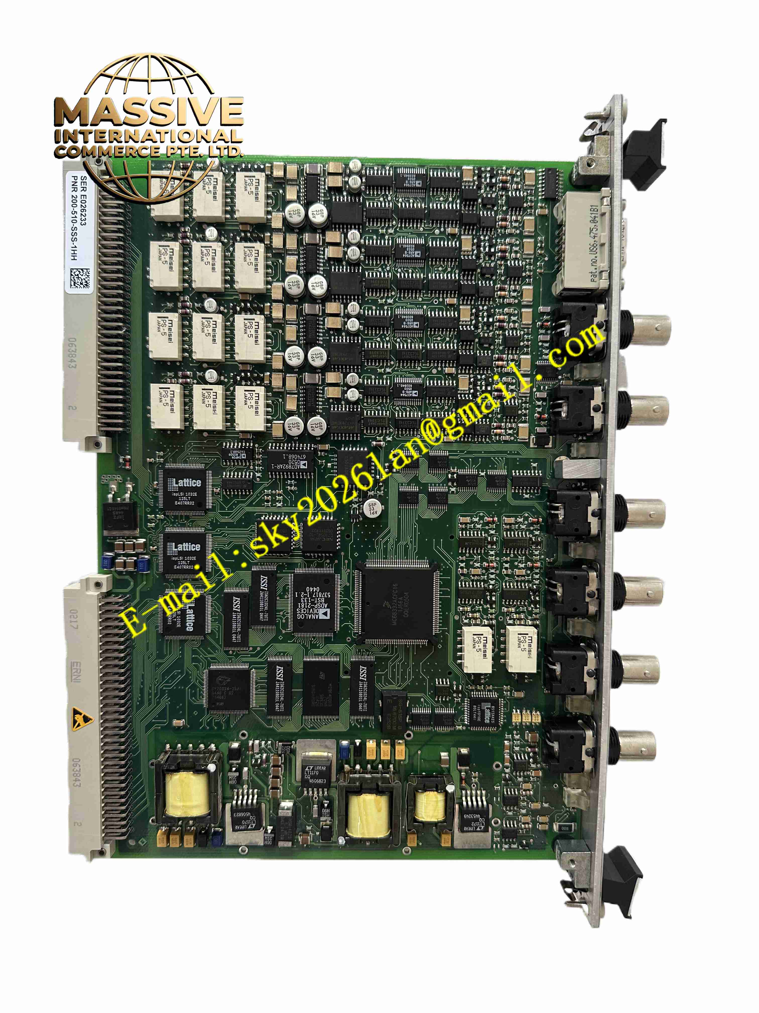
VIBRO-METER MPC4 200-510-SSS-1HH
Technical Specifications
System family: Vibro-Meter VM600 MPS
Card type: machinery protection processing card
Dynamic signal channels: 4, individually programmable
Tachometer channels: 2, individually programmable
Dynamic input DC range: 0 to +20 V or 0 to -20 V
Dynamic input AC range: up to ±10 V
Common-mode voltage range: -50 V to +50 V
CMRR: greater than 60 dB at 50 Hz
Crosstalk: -72 dB
Input impedance: 200 kΩ
Analog frequency range: DC to 60 kHz (-3 dB)
Relative vibration frequency range: 0.1 Hz to 10 kHz
Gap/position frequency range: DC to 1 Hz
Amplitude accuracy: ±1 percent of full scale for vibration and gap/position
Linearity error: less than ±1 percent
Analog output: 0 to 10 V and 4 to 20 mA via IOC4T/IOC4S
Buffered raw output impedance: 50 Ω
Buffered raw output bandwidth: DC to 10 kHz (-0.1 dB, load greater than 1 MΩ); DC to 40 kHz (-3 dB)
Phase error: less than 5° from DC to 1 kHz; less than 30° from DC to 10 kHz
Power supply: provided by VM600 rack backplane
Operating temperature: typically 0 to 55 °C in a ventilated control cabinet
Protection class: IP20
MTBF: ≥100,000 hours
Versions available: standard, isolated circuit, and SIL safety versions
Compatible racks: VM600 ABE04x series
Functional Features
Four programmable dynamic signal channels
Two programmable tachometer channels
Real-time DSP-based vibration processing
Broadband and narrowband digital filtering
Integration and differentiation processing
RMS, average, true peak, and true peak-to-peak rectification
Order tracking for amplitude and phase
Sensor-to-target gap measurement
Relative and absolute vibration measurement
Smax, eccentricity, and thrust position monitoring
Absolute and differential casing expansion measurement
Dynamic pressure monitoring
Programmable alert and danger setpoints
Adaptive alarm levels based on speed or external signals
Front-panel BNC connector for buffered raw signal analysis
Front-panel LED status and alarm indication
Hot-swappable module design
Sensor and signal conditioner power supply
Continuous measurement chain diagnostics
Supports metric and imperial units
Configurable alarm time delay, hysteresis, and latching
Application Scenarios
Steam turbine vibration and speed monitoring
Gas turbine mechanical protection
Centrifugal compressor protection
Generator and motor vibration monitoring
Pump and fan condition monitoring
Gearbox vibration surveillance
Industrial rotating equipment protection
API 670 machinery protection systems
Power generation plant monitoring
Oil and gas rotating machinery protection
Performance Parameters
Dynamic channels: 4
Tachometer channels: 2
Vibration amplitude accuracy: ±1 percent of full scale
Gap/position accuracy: ±1 percent of full scale
Linearity: less than ±1 percent
CMRR: greater than 60 dB at 50 Hz
Crosstalk: -72 dB
Analog bandwidth: DC to 60 kHz
Buffered output bandwidth: DC to 40 kHz (-3 dB)
Alarm response: real-time DSP-based processing
Diagnostics: continuous OK system monitoring
MTBF: ≥100,000 hours
Material Composition
Industrial printed circuit board assembly
Digital signal processor
Analog input conditioning circuits
Tachometer input circuits
Relay and output driver circuits associated with IOC4T/IOC4S
BNC front-panel connector
LED status indicators
Backplane connector interface
Metal shielding and grounding components
Protective conformal coating
Thermoplastic and metal module housing
Structural Features
VM600 plug-in card format
Front-panel BNC connector for raw signal access
Front-panel LED indicators per channel and for card status
Backplane connector for rack integration
Paired operation with IOC4T or IOC4S I/O card
Compact single-slot module width
Rail-guided insertion into VM600 rack
Label plate for part number and identification
Designed for 19-inch VM600 rack installation
Working Principle
Vibration, displacement, and speed sensors connected to the system send analog signals to the MPC4 card. The card conditions the signals, applies digital filtering, integration, differentiation, and rectification, and computes vibration amplitude, phase, position, and speed values. Tachometer inputs provide rotational reference for order tracking and speed-dependent alarm adaptation. When measured values exceed programmed alert or danger thresholds, the card triggers internal digital outputs that drive relay cards such as IOC4T, RLC16, or IRC4. Buffered raw signals are available on the front-panel BNC for analysis. The OK system continuously monitors sensor and signal chain integrity.
Installation Requirements
Install in a compatible rack such as ABE040, ABE042, or ABE045
Pair the MPC4 with the correct IOC4T or IOC4S card
Insert the card into the designated rack slot until fully seated
Connect dynamic sensors and tachometer sensors according to the I/O assignment
Configure channel type, range, filter, and alarm setpoints in MPSx software
Verify sensor power supply configuration
Ensure rack ventilation meets environmental limits
Ground the rack and shield sensor cables properly
Confirm alarm routing to relay outputs and external trip systems
Usage Precautions
Do not exceed the rated input voltage ranges
Verify the correct IOC4T/IOC4S pairing
Do not remove the card during active trip conditions without authorization
Check LED indicators and diagnostics during commissioning
Keep firmware and configuration consistent with the protection philosophy
Use shielded cables for vibration and tachometer signals
Avoid exposing the card to moisture or conductive dust
Replace only with genuine Vibro-Meter MPC4 cards
Refer to the official MPC4 manual for final electrical and mechanical limits