Description
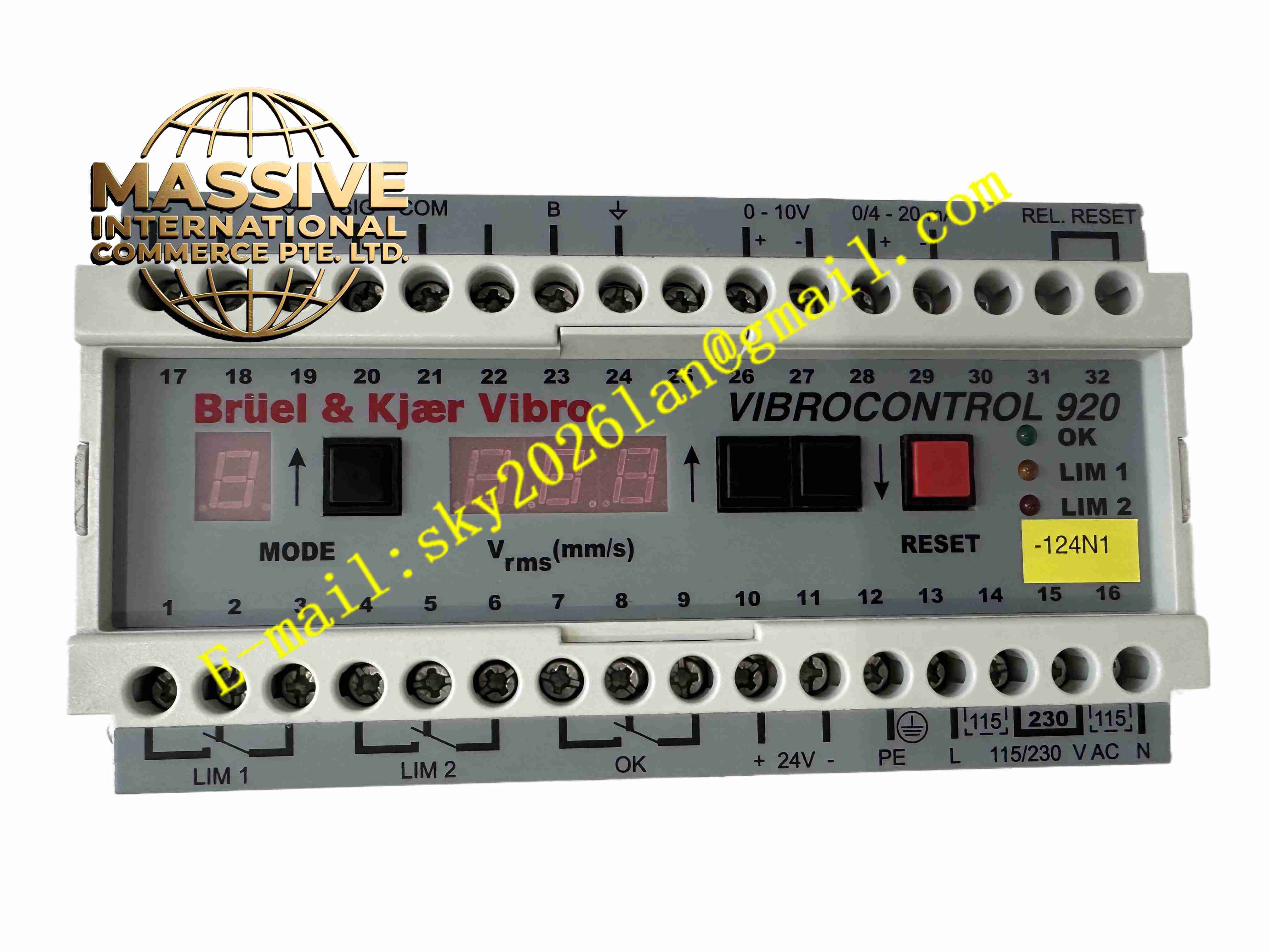
Vibro-Meter VC-920 VIBROCONTROL 920
Technical Specifications
Manufacturer: Vibro-Meter / Schenck / Brüel & Kjær Vibro product family
Product name: VIBROCONTROL 920
Abbreviation: VC-920
Product type: single-channel vibration monitoring instrument
Measured variable: vibration velocity RMS value in mm/s
Frequency range: 1 to 1000 Hz or 10 to 1000 Hz depending on configuration
Accuracy: ±5 percent relative to the displayed value
Sensor input: vibration velocity sensor or vibration acceleration sensor
Acceleration integration: converts acceleration sensor signals to velocity values by internal integration
Alarm outputs: two adjustable alarm relays with configurable delay
Analog output: buffered analog output for connection to external systems
Display: three-digit numerical display for vibration value
Power supply: AC 115 V or AC 230 V, 41 to 62 Hz, or DC +18 to +32 V
Power consumption: approximately 12 W
Enclosure: plastic housing, IP20
Weight: approximately 1 kg
Connection: screw terminal block for power, sensor, relay, and analog signals
Functional Features
Continuous bearing and housing vibration monitoring
Direct display of vibration velocity RMS value in mm/s
Supports vibration velocity and acceleration sensors
Two adjustable alarm limit values
Configurable alarm response delay to avoid false alarms
Analog output for connection to DCS, PLC, or recording systems
Internal OK monitoring for power supply, microprocessor, and sensor function
Parameter configuration through front-panel keys
LED indication for alarm and fault conditions
Compact single-channel monitoring design
Application Scenarios
Rotating machinery vibration monitoring
Industrial fan vibration surveillance
Pump bearing condition monitoring
Compressor vibration protection
Gearbox vibration monitoring
Motor bearing monitoring
Turbine auxiliary vibration surveillance
Cement industry rotating equipment monitoring
Power plant auxiliary machinery monitoring
General industrial machine protection systems
Performance Parameters
Measurement type: vibration velocity RMS value
Frequency range: 1 to 1000 Hz or 10 to 1000 Hz
Accuracy: ±5 percent depending on display conditions
Alarm channels: two independent alarm relays
Alarm delay: adjustable to prevent transient false alarms
Analog output: buffered output for external monitoring
Self-monitoring: OK monitoring for power, processor, and sensor
Reliability: industrial vibration monitoring design
Service life: dependent on operating environment and sensor condition
Material Composition
Plastic enclosure
Internal printed circuit board assembly
Microprocessor-based measurement circuitry
Sensor input conditioning circuit
Relay output circuit
Analog output circuit
Screw terminal block
LED status indicators
Power supply module
Protective internal shielding
Identification label with VC-920 designation
Structural Features
Compact panel-mount or cabinet-mount housing
Three-digit front display
Front-panel configuration keys
LED indicators for alarm and status
Screw terminal connections for all signals
Sensor input terminal
Two relay output terminals
Analog output terminal
Power supply terminal
IP20 plastic enclosure
Clear model identification on the front or side label
Working Principle
The VC-920 receives a vibration signal from a connected velocity or acceleration sensor. When an acceleration sensor is used, the instrument integrates the signal to obtain a vibration velocity value. The measured value is displayed as an RMS value in mm/s. The instrument continuously compares the measured vibration level with two user-defined alarm limits. If a limit is exceeded for longer than the configured delay time, the corresponding relay is activated. The internal OK monitoring function checks the power supply, microprocessor operation, and sensor connection to detect instrument or sensor faults.
Installation Requirements
Install in a dry, clean, and vibration-free control cabinet environment
Mount the instrument securely according to the mechanical drawing
Connect only compatible vibration velocity or acceleration sensors
Verify sensor sensitivity settings before commissioning
Use shielded sensor cables and follow recommended grounding practices
Connect the correct power supply voltage according to the nameplate
Verify relay and analog output wiring before enabling alarms
Configure alarm limits and delay times according to machine requirements
Usage Precautions
Do not connect incompatible sensors without verifying sensitivity settings
Ensure the correct AC or DC supply voltage is selected
Do not exceed the rated environmental limits of the instrument
Keep the IP20 enclosure protected from moisture and conductive dust
Verify sensor cable integrity during periodic maintenance
Test alarm relays and analog output during commissioning
Replace only with genuine Vibro-Meter / Schenck / Brüel & Kjær Vibro parts or approved equivalents
Refer to the official VIBROCONTROL 920 manual for final wiring, parameter setting, and safety limits