Description
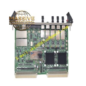
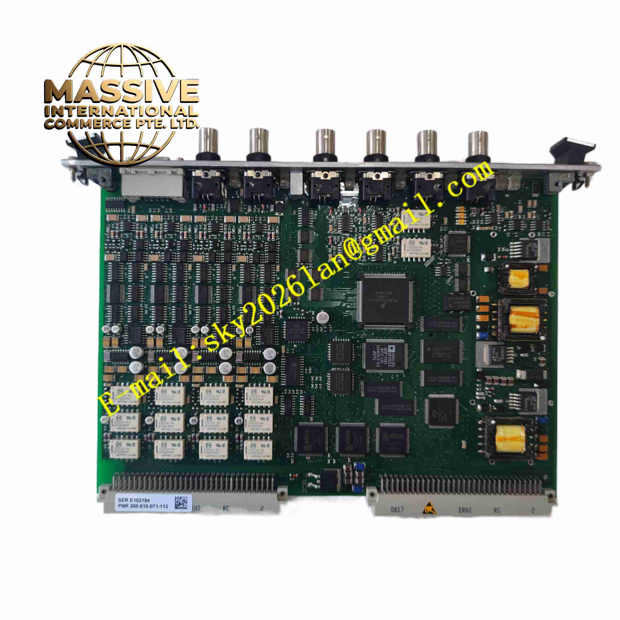
Vibro-Meter VM600 MPC4 200-510-071-113 / 200-510-111-034
Technical Specifications
- Brand: Vibro-Meter, part of Meggitt Sensing Systems
- Model: MPC4
- Part numbers: 200-510-071-113, 200-510-111-034
- Module type: 4-channel mechanical protection processing card
- System platform: VM600 Machinery Protection System
- Dynamic channels: 4 independently configurable dynamic signal channels
- Tachometer channels: 2 independently configurable tachometer/speed channels
- Supported sensors: IEPE accelerometers, velocity sensors, eddy current proximity probes, displacement sensors and related signal conditioners
- Measurement capabilities: Relative vibration, absolute vibration, Smax, eccentricity, thrust position, casing absolute and differential expansion, displacement and dynamic pressure
- Digital processing: Digital filtering, integration/differentiation, RMS/average/true peak/true peak-to-peak rectification, order tracking and gap measurement
- Alarm functions: Programmable Alert and Danger setpoints with time delay, hysteresis and latching
- Self-diagnostics: Power-on self-test and continuous OK system monitoring
- Mounting: Front slot of VM600 ABE04x or ABE056 rack
- Power supply: Supplied by VM600 rack backplane
- Software: Configured using VM600 MPSx software
- Safety: SIL-rated variants are available depending on configuration
Functional Features
- Provides continuous online mechanical protection for rotating machinery.
- Processes up to four dynamic channels and two tachometer channels simultaneously.
- Supports broadband and narrowband digital filtering.
- Monitors vibration amplitude and phase in order tracking mode.
- Generates internal digital alarm outputs for Alert and Danger conditions.
- Drives relay outputs through the associated IOC4T card.
- Provides buffered raw sensor signals for analysis.
- Supports analog outputs for vibration and speed signals.
- Performs continuous measurement chain monitoring to detect sensor faults.
- Supports hot-swap replacement within the VM600 rack.
- Available in Standard, Isolated Circuit and SIL versions.
Application Scenarios
- Steam turbine vibration protection.
- Gas turbine monitoring and protection.
- Centrifugal compressor protection.
- Pump and fan vibration monitoring.
- Generator bearing vibration protection.
- Thrust position and axial displacement monitoring.
- Casing expansion monitoring.
- Basic condition monitoring and machinery protection systems.
Performance Parameters
- 4 dynamic channels and 2 tachometer channels per card.
- Real-time DSP-based signal processing.
- Simultaneous amplitude and phase monitoring.
- Programmable Alert and Danger alarm levels.
- Adaptive alarm and danger levels depending on speed or external information.
- Continuous sensor and measurement chain diagnostics.
- Front-panel BNC connectors for buffered raw signal access.
- Front-panel LEDs for status, alarm and fault indication.
- DC input range: 0 to +20 V or 0 to -20 V depending on configuration.
- AC input range: up to ±10 V.
- Common-mode voltage range: -50 V to +50 V.
- CMRR: greater than 60 dB at 50 Hz.
- Crosstalk: -72 dB.
- Input impedance: 200 kΩ.
- Relative vibration frequency range: 0.1 Hz to 10 kHz.
- Gap/position frequency range: DC to 1 Hz.
- Amplitude accuracy: ±1 percent of full scale for vibration and gap/position.
- Linearity error: less than ±1 percent.
Material Composition
- Industrial printed circuit board.
- DSP and processor circuits.
- Analog input conditioning circuits.
- Tachometer input circuits.
- Digital alarm output circuits.
- Buffered analog output circuits.
- Backplane interface circuits.
- Front-panel BNC connectors.
- Status LED indicators.
- Protective metal front panel and card frame.
Structural Features
- 6U rack module design.
- Front-mounted processing card.
- Forms a card pair with an IOC4T I/O card installed at the rear.
- Front-panel BNC connectors for raw sensor signal access.
- Front-panel LEDs for channel status and alarms.
- Module height: 6U, approximately 262 mm.
- Module width: approximately 20 mm.
- Module depth: approximately 187 mm.
- Module weight: approximately 0.40 kg.
- Designed for installation in ABE040, ABE042 or ABE056 racks.
Working Principle
The MPC4 receives dynamic sensor signals and tachometer signals through the associated IOC4T interface card. It amplifies, filters and digitizes the signals, then calculates vibration amplitude, phase, speed and position parameters. The card continuously compares measured values with programmed Alert and Danger setpoints. When an alarm condition occurs, it generates internal digital outputs that drive relay cards or analog outputs. The OK system monitors sensor supply, signal level and measurement chain integrity. If a fault is detected, the card reports the condition through front-panel LEDs and system diagnostics.
Installation Requirements
- Install the MPC4 in the front slot of a compatible rack.
- Install the matching IOC4T card in the rear slot to form a card pair.
- Verify that the rack power supply is within specification.
- Use approved sensor cables and shielded wiring.
- Ground sensor shields according to installation requirements.
- Configure channel parameters using MPSx software.
- Verify sensor type, range and alarm settings before commissioning.
- Confirm that the MPC4 revision is compatible with the installed IOC4T and rack firmware.
Precautions for Use
- Only qualified vibration protection personnel should configure or service the card.
- Do not modify alarm setpoints without authorization.
- Verify sensor and cable integrity before relying on protection functions.
- Investigate OK system faults before returning the machine to service.
- Do not remove the card during critical machine operation unless permitted by plant procedures.
- Back up configuration data before replacement.
- Use only genuine Vibro-Meter MPC4 and IOC4T card pairs.
- Refer to the official Vibro-Meter manual for exact specifications and wiring.