Description
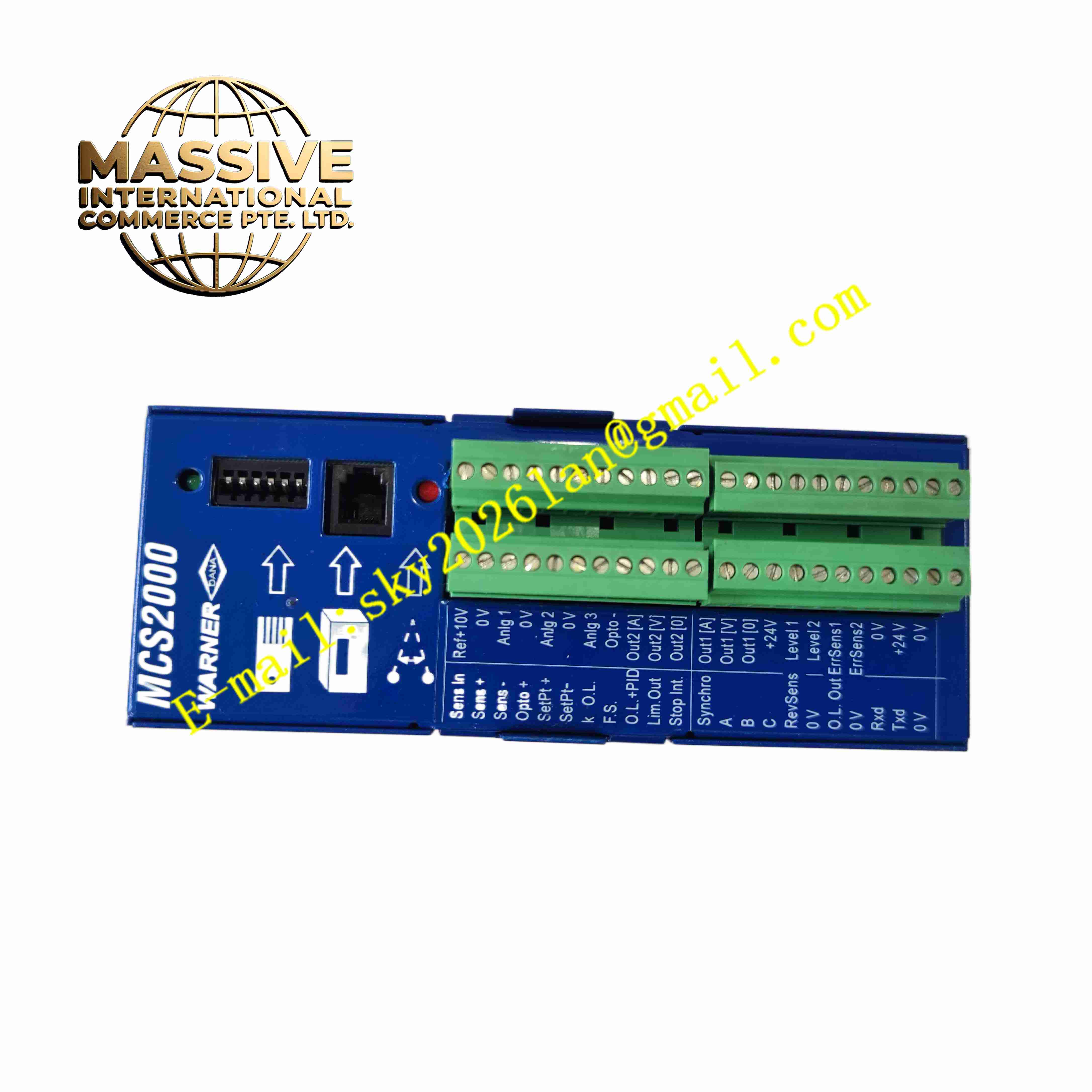
Warner Electric MCS2000-ECA
Technical Specifications DC regulated output for clutch/brake coil; Adjustable ramp up and ramp down time; Digital fault detection; Relay alarm output; Supply voltage 115/230V AC; DIN rail mounting; Protection class IP20.
Functional Features Adjustable soft acceleration and deceleration ramp; Closed-loop coil current regulation; Over-current and coil open circuit fault diagnosis; Relay contact alarm output for fault events; Manual test function; Surge suppression for inductive coil load; Status LED indicators.
Application Scenarios Material handling conveyor clutch brake control; Printing machinery web tension control; Packaging machine intermittent motion; Metal processing stamping equipment clutch brake system.
Performance Parameters Operating ambient temperature -10℃ to +60℃; Storage temperature -40℃ to +85℃; Relative humidity 5% to 95%, no condensation; EMC meets industrial machine standard.
Material Composition Flame-retardant plastic DIN rail housing; Multi-layer power control PCB; Power regulation circuit; Current sampling components; Electromechanical alarm relay; Brass nickel-plated screw terminals; LED status indicators.
Structural Characteristics DIN rail compact rectangular housing; Front panel LED indicators for power, fault and operating status; Upper and lower terminal blocks for AC power, clutch brake coil wiring and alarm output; Internal separation of power regulation circuit and fault detection circuit.
Working Principle AC input power converts to regulated DC excitation current for clutch or brake coil. Microcontroller controls current rising and falling slope to realize soft start and soft stop. Current sampling circuit monitors coil current continuously. If coil open circuit or over-current occurs, module triggers relay alarm output.
Installation Requirements Mount module on cabinet standard DIN rail. Separate clutch brake coil wiring from low-level signal cables. Complete cabinet protective earthing. Set ramp time parameters according to mechanical load requirement. Execute manual test to verify clutch brake operation.
Usage Notes Cut off power before wiring modification. Do not exceed rated coil current output. Check coil insulation resistance periodically. Avoid strong electromagnetic interference near the module. Keep terminal block free of dust and conductive contamination.