Description
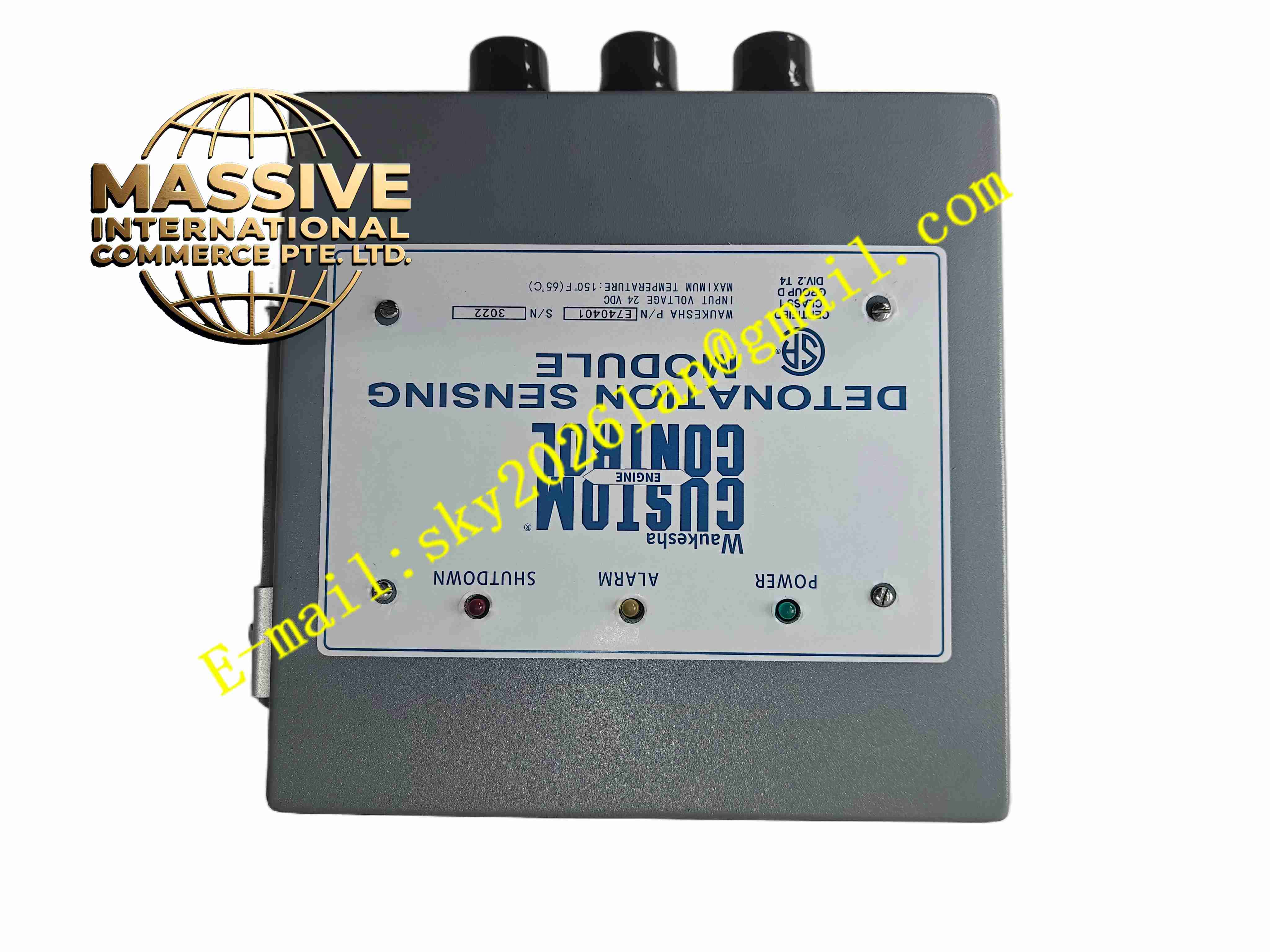
WAUKESHA E740401
Technical Specifications:
- Power Supply: 24V DC
- Input Signals: Crankshaft position, camshaft position sensor pulses
- Output: Ignition drive signals for engine ignition coils
- Number of Cylinder Channels: Matched to Waukesha multi-cylinder gas engine
- Operating Temperature: -20°C to +70°C
- Storage Temperature: -40°C to +85°C
- Humidity: 5%~95% non-condensing
- Protection: Overvoltage, overcurrent and short circuit protection for ignition outputs
Function Features:
- Real-time ignition timing calculation based on crankshaft and camshaft position
- Sequential cylinder ignition firing control for gas engine
- Ignition coil drive output and dwell time control
- Detection of misfire, missing pulse and sensor fault
- Engine speed calculation from crank pulse signal
- Fault status output to engine control panel
- Configurable timing advance curves for varying engine load and speed
Application Scenarios:
- Waukesha large gas generator engines for power generation
- Gas compression reciprocating engines
- Biogas and natural gas engine power plants
- Engine maintenance spare parts replacement for Waukesha engine systems
Material Composition:
- Housing: Cast aluminum alloy metal enclosure
- PCB: Multilayer FR4 fiberglass circuit board with conformal coating
- Power Components: IGBT ignition drive semiconductors
- Control Core: Industrial microcontroller and pulse capture chips
- Terminals: Heavy duty screw terminals for power, sensor and ignition wiring
Structural Features:
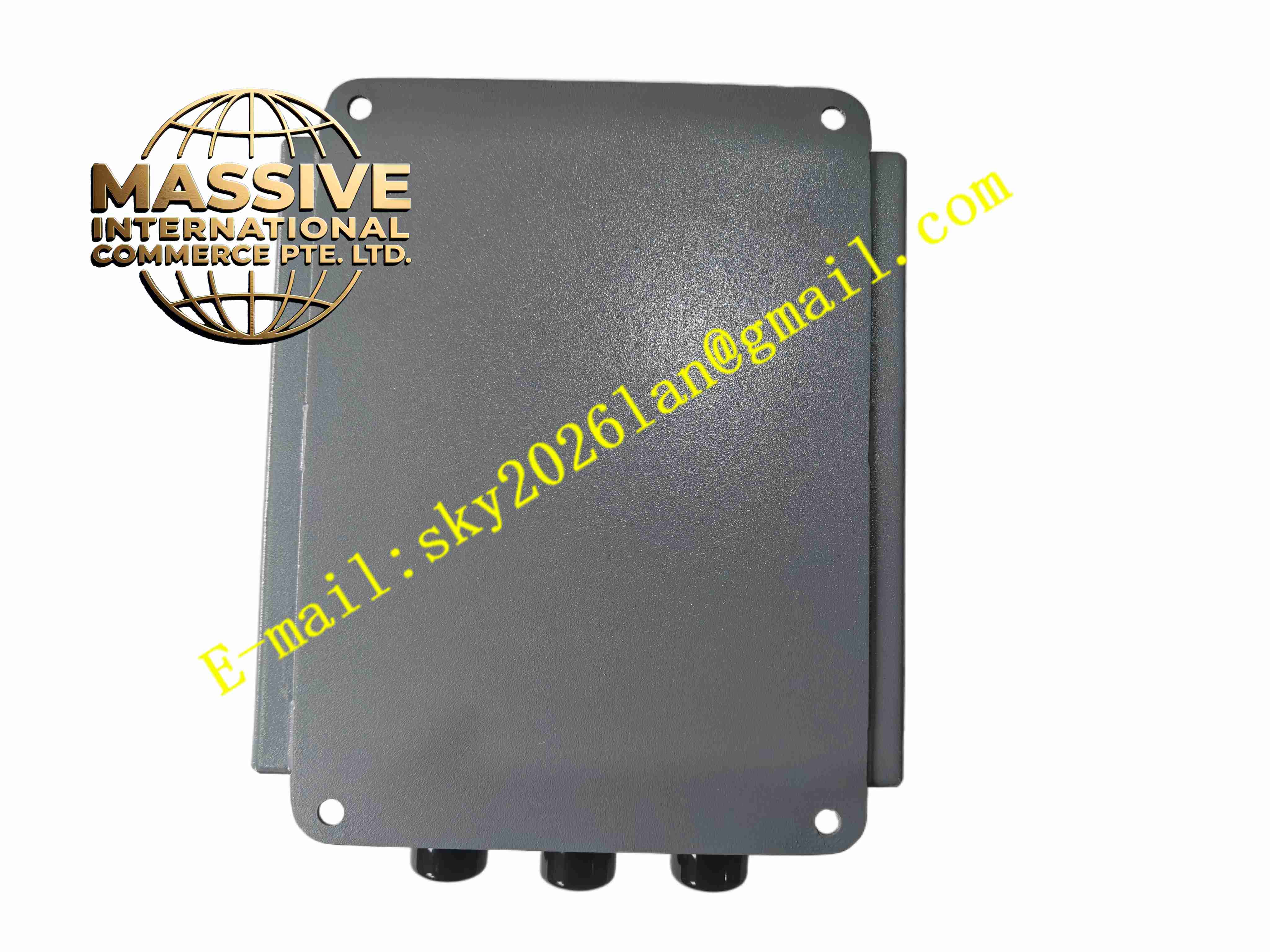
- Sealed cast aluminum housing for engine compartment mounting
- Multiple separated terminal blocks for power, sensor inputs and ignition outputs
- Front panel LED status indicators for power, run and fault
- Internal heat sink for power device heat dissipation
- Vibration resistant internal component soldering for engine environment
Working Principle: Crankshaft and camshaft sensors send pulse signals to the module. The microcontroller calculates engine speed and crank angle position. It references pre-programmed timing curve and generates ignition trigger signals at the correct crank angle for each cylinder. Drive circuits activate ignition coils with defined dwell time. Misfire and pulse loss detection continuously monitor ignition operation and trigger fault alarm when abnormal conditions occur.
Installation Requirements:
- Mount module on rigid vibration-damped bracket near engine
- Separate low voltage sensor wiring from high voltage ignition wiring
- Use shielded twisted pair for crank and cam sensor cables
- Implement reliable protective earth connection
- Maintain free air circulation around housing for heat dissipation
- Keep away from exhaust and high-temperature engine components
Usage Notes:
- Confirm engine cylinder configuration and timing parameters before power on
- Do not touch ignition output terminals when engine is running
- Inspect terminal tightness regularly due to engine vibration
- Prevent oil, water and gas condensate entering module housing
- Disconnect 24V DC power before wiring modification
- Perform ignition timing verification after module replacement