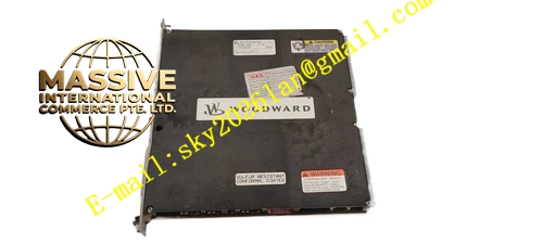
Description
WOODWARD 5466-258
Technical Specifications:
- Brand: Woodward
- Model: 5466-258
- Product Type: Simplex Discrete I/O Module
- System Compatibility: MicroNet Plus, Vertex-Pro
- External Input Voltage: 18 to 32 VDC
- Power Input: 18 to 32 VDC
- Power Consumption: 6.5 Watts at 24 VDC
- Chassis Compatibility: 8-slot or 14-slot chassis
- Redundancy: Supports Simplex and Redundant system configurations
Functional Features:
- Discrete Signal Handling: Manages digital inputs (status monitoring) and digital outputs (control commands).
- Hot-Swappable: Supports real-time replacement of faulty nodes without shutting down the network.
- Address Configuration: Rotary switches for setting module address (1 to 10).
- Flexible Mounting: Can be installed in any slot within the compatible chassis.
Application Scenarios:
- Industrial automation systems requiring digital signal expansion.
- Turbine control systems for valve status and limit switch monitoring.
- Process control applications.
Performance Parameters:
- Voltage Range: 18-32 VDC
- Power Draw: 6.5 W
Material Composition:
- Standard industrial PCB assembly.
- Plastic module casing with metal connectors.
Structural Features: The module features terminal blocks for field wiring and a backplane connector for chassis integration. It includes rotary switches for address setting.
Working Principle: The module reads the state of connected field devices (open/closed) and sends this data to the controller via the chassis backplane. Conversely, it receives commands from the controller to switch output relays or transistors on or off.
Installation Requirements:
- Mount on a DIN rail or within a compatible Woodward chassis.
- Set the address switches to match the system configuration.
- Connect 24 VDC power and field wiring.
Usage Notes:
- When replacing a node, ensure the replacement module has the same address switch settings.
- Use the application software to reset the node after replacement to clear communication faults.
- Ensure the power supply is stable within the 18-32 VDC range.