Description
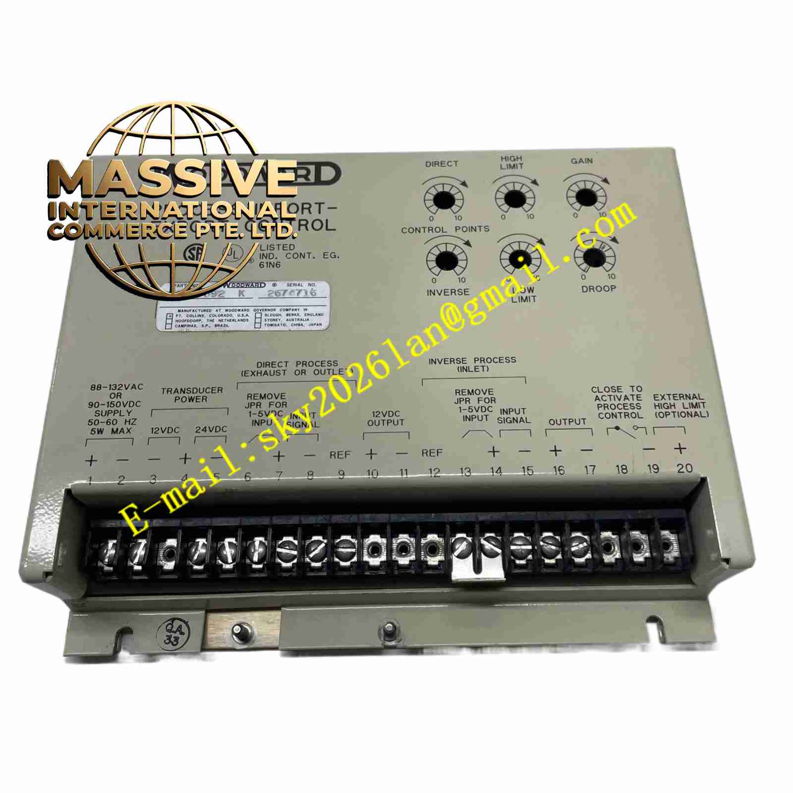
Woodward 9905-228
Technical Specifications
- Product Type: Electronic Load Sharing and Speed Control Module.
- System Compatibility: Woodward 2301A LSSC System.
- Input Signals: Accepts signals from magnetic speed sensors and current transformers.
- Output: Analog or PWM signals for actuator control.
Functional Features
- Isochronous and Droop Control: Supports both isochronous (constant speed) and droop (load-dependent speed) control modes for flexible paralleling.
- Active Load Sharing: Continuously monitors generator output and adjusts fuel/steam to ensure equal load distribution among parallel units.
- Soft Load Transfer: Prevents sudden load shocks during generator synchronization and paralleling.
- Adjustable Ramps: Features adjustable idle-to-rated ramp times for smooth engine acceleration and deceleration.
Application Scenarios
Widely deployed in diesel generator sets, co-generation plants, marine power systems, and microgrids where multiple generators must operate in parallel to supply a common bus.
Performance Parameters
- Speed Regulation: Highly precise, typically within ±0.25% of setpoint in isochronous mode.
- Load Sharing Accuracy: Ensures balanced load distribution within ±3% of rated generator capacity.
- Response Time: Fast dynamic response to sudden load changes to maintain frequency stability.
Material Composition
Housed in a rugged, industrial-grade enclosure designed to dissipate heat and protect against electromagnetic interference (EMI). Internal circuitry utilizes high-reliability electronic components conformal-coated for environmental protection.
Structural Characteristics
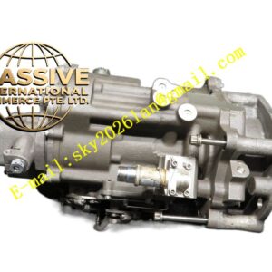
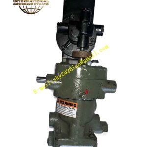
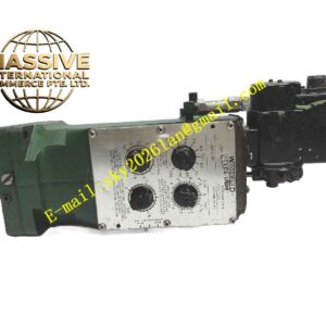
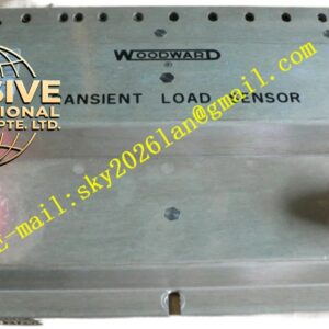
A compact, modular electronic board designed to plug into a standard 2301A baseplate or rack. Features front-panel adjustment potentiometers for speed, load gain, and droop settings, along with LED status indicators.
Working Principle
The module continuously compares the actual engine speed (from a magnetic pickup) with a reference setpoint. Simultaneously, it monitors the generator’s current output. Based on the selected control mode (droop or isochronous), the internal microprocessor calculates the necessary fuel adjustment and outputs a control signal to the engine governor actuator to maintain target speed and load balance.
Installation Requirements
Mount in a clean, dry control cabinet. Connect shielded cables for speed sensor and current transformer inputs to prevent noise interference. Ensure proper grounding of the control system.
Usage Precautions
- Always verify current transformer (CT) phasing before commissioning to prevent unstable load sharing.
- Adjust gain and stability parameters carefully to avoid hunting (oscillating speed/load).
- Handle with ESD (Electrostatic Discharge) precautions to prevent damage to internal microprocessors.