Description
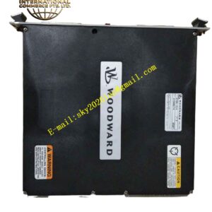
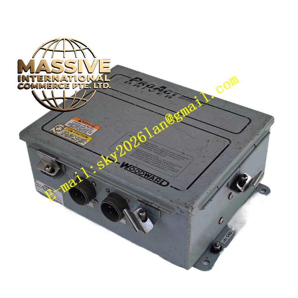
Woodward 9905-390
Technical Specifications
- Product Series: 2301A / 9905 Series Digital Governor.
- Control Modes: Isochronous (constant speed) or Droop (load-dependent speed).
- Inputs: Magnetic pickup (speed), CTs/PTs (load sensing), and various analog/digital status inputs.
- Outputs: Actuator drive outputs and programmable relay outputs.
- Communication: Supports serial communication for integration with plant DCS or SCADA systems.
Functional Features
- Precision Governing: Maintains engine speed within tight tolerances under rapidly changing load conditions.
- Load Sharing: Actively manages active load sharing among parallel generator sets to prevent circulating currents.
- Engine Protection: Monitors critical parameters (oil pressure, coolant temperature, overspeed) and initiates shutdowns or alarms when limits are exceeded.
- Programmable Logic: Allows users to customize control strategies and protection curves via front-panel menus or software.
Application Scenarios
Extensively used in prime power, standby, and continuous power generation applications, including data centers, hospitals, marine vessels, and industrial manufacturing plants.
Performance Parameters
- Speed Regulation: Excellent transient response and steady-state accuracy.
- Scan Rate: High-speed digital processing ensures real-time response to engine dynamics.
Material Composition
Housed in a rugged, painted steel enclosure designed for panel mounting. Internal printed circuit boards feature conformal coating to protect against moisture, dust, and corrosive gases.
Structural Characteristics
A compact, front-accessible module featuring an intuitive LED display and membrane keypad for local parameter adjustment, calibration, and diagnostics. All field wiring connections are made via removable terminal blocks.
Working Principle
The controller continuously samples the engine’s speed via a magnetic pickup and compares it to a user-defined setpoint. Based on the error, it calculates the required fuel adjustment and outputs a PWM (Pulse Width Modulated) signal to an electrohydraulic actuator. In parallel operation, it also monitors electrical load and adjusts the fuel rack to proportionally share the kilowatt burden.
Installation Requirements
Mount in a clean, dry control panel with adequate ventilation. Route speed sensing cables away from high-voltage power lines to prevent electromagnetic interference. Ensure the actuator wiring polarity is correct.
Usage Precautions
- Always configure the correct control mode (Isochronous vs. Droop) before paralleling generators.
- Verify all engine protection setpoints match the engine manufacturer’s specifications.
- Perform regular functional tests of the overspeed protection circuit.