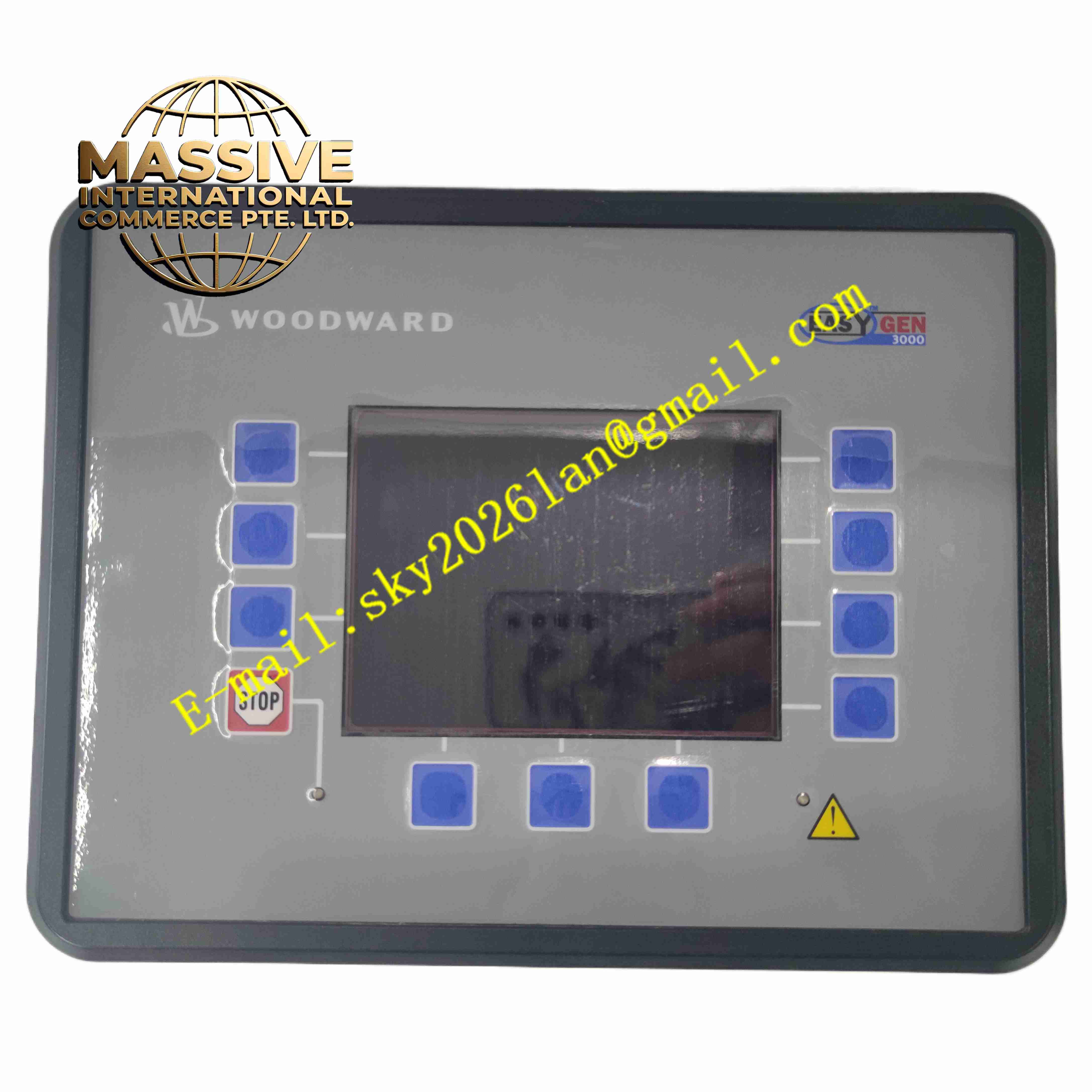
Description
WOODWARD EASYGEN 3500-5
Technical Specifications
- Product Type: Engine generator paralleling and protection controller
- Measurement Type: True RMS voltage, current, frequency and power measurement
- Voltage Input Range: 120 VAC to 690 VAC
- Power Supply: 8 VDC to 36 VDC battery supply
- Communication Ports: CANopen, J1939, Modbus RTU, USB service port
- Max Supported Gensets: Up to 32 generator units in parallel network
- Protection Functions: Overvoltage, undervoltage, overfrequency, underfrequency, overcurrent, reverse power, loss of excitation
- Display: Built-in LCD graphic display
- Protection Class: Front panel IP65
- Operating Temperature: -40 °C to +70 °C
- Certifications: CE, UL/cUL, CSA, ABS, Lloyd’s Register marine certification
Functional Features
- Automatic synchronization and paralleling between generator sets and utility mains.
- Active and reactive load sharing for multiple parallel gensets with high stability.
- Complete engine start/stop sequence control including pre-lubrication and cool-down timing.
- Comprehensive generator electrical protection and engine fault alarm and trip functions.
- Built-in LogicsManager programmable logic editor to customize interlock sequences.
- J1939 CAN bus direct communication to modern engine ECUs for engine monitoring and control.
- Modbus RTU slave interface to transmit real-time data to SCADA and DCS systems.
- AMF automatic mains failure function to start genset and transfer load upon utility power loss.
- Peak shaving and import/export power control for cogeneration CHP systems.
- Event and alarm data logging with timestamp storage for post-fault analysis.
Application Scenarios
- Hospital and data center emergency backup power plants
- Industrial multi-generator parallel power stations
- Marine vessel onboard generator power management
- Cogeneration combined heat and power systems
- Rental mobile generator fleet parallel operation
Material Composition
- Front panel: Reinforced flame-retardant plastic with polycarbonate display window
- Main housing: Die-cast aluminum alloy rear enclosure
- Main PCB: FR4 industrial printed circuit board with conformal coating
- Signal transformers: High precision current and voltage sensing transformers
- Terminals: Copper alloy screw terminals for power and signal wiring
- Sealing gasket: Foam rubber sealing ring for front panel ingress protection
Structural Characteristics
- Panel flush mounting structure, front panel exposed on control cabinet door.
- Rear aluminum housing contains PCB, transformers and all wiring terminals.
- Front LCD screen and tactile operation keys for local parameter adjustment.
- Multiple communication connectors located on the rear side.
- Sealing gasket between front frame and cabinet cutout to achieve IP65 front protection.
- Internal layout separates high voltage measurement circuits and low voltage logic circuits.
Working Principle The controller samples generator voltage, current and frequency signals via internal voltage and current transformers. It compares generator electrical parameters with bus or utility mains parameters to execute synchronization control. It sends speed and voltage adjustment commands to engine governor and AVR for frequency and voltage matching. When parallel condition is satisfied, the controller sends breaker closing command. The load sharing algorithm distributes real and reactive load evenly across all running gensets. The built-in logic engine executes user-defined interlock sequences, and fault protection circuits trigger breaker trip and engine shutdown when abnormal electrical conditions are detected.
Installation Requirements
- Cut standard rectangular cutout on control cabinet door for flush panel mounting.
- Use shielded twisted pair wiring for CT and VT measurement signals.
- Separate power battery wiring from low-level signal wiring.
- Complete battery negative protective earth connection.
- Install external current transformers with correct polarity matching.
- Perform CT/VT ratio configuration and phase sequence calibration after installation.
- Use Woodward PC service software to download project configuration.
Usage Notes
- Verify CT wiring polarity before energizing the controller.
- Do not apply voltage exceeding rated measurement range to voltage inputs.
- Regularly back up configuration files to external storage device.
- Prevent conductive dust accumulation on rear terminal area.
- Isolate controller from high vibration locations.
- Recheck all protection setpoints before placing generator into automatic mode.
- Update firmware only during scheduled equipment shutdown.