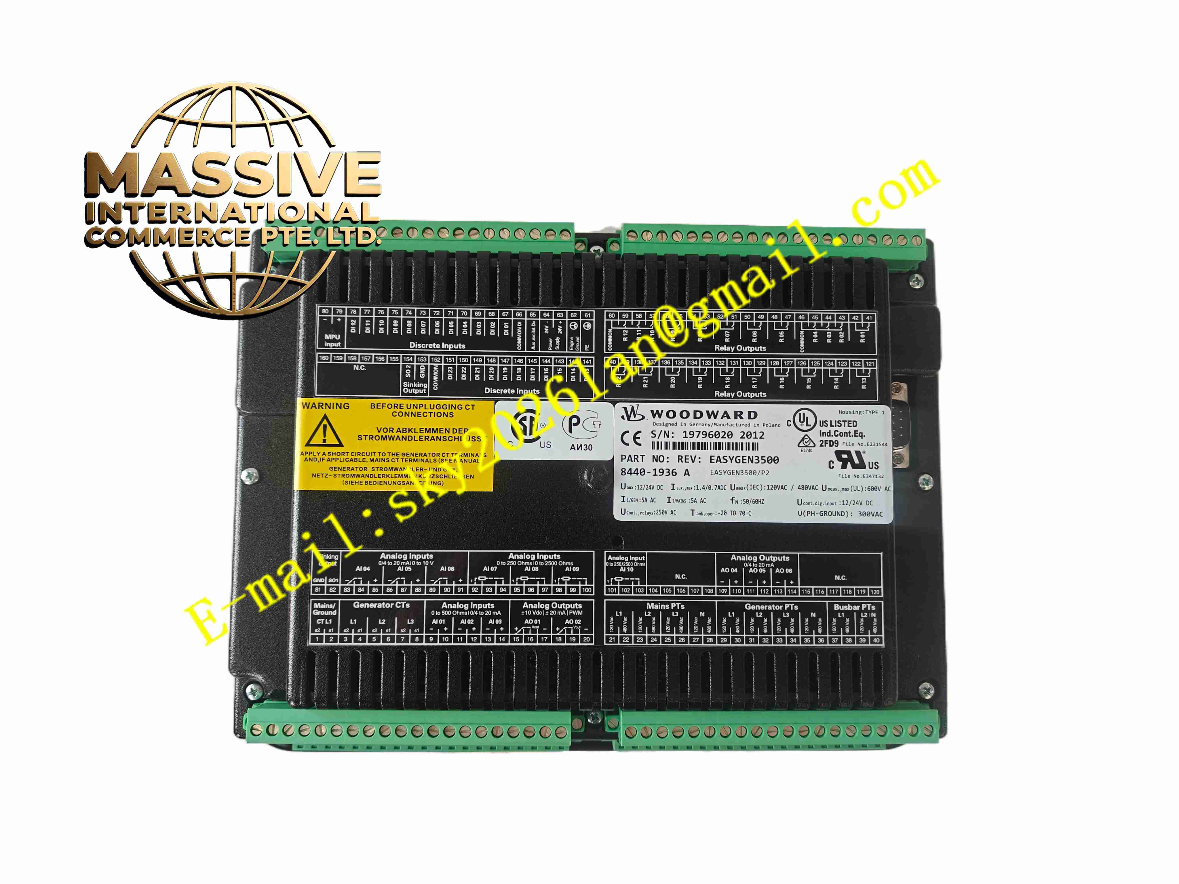
Description
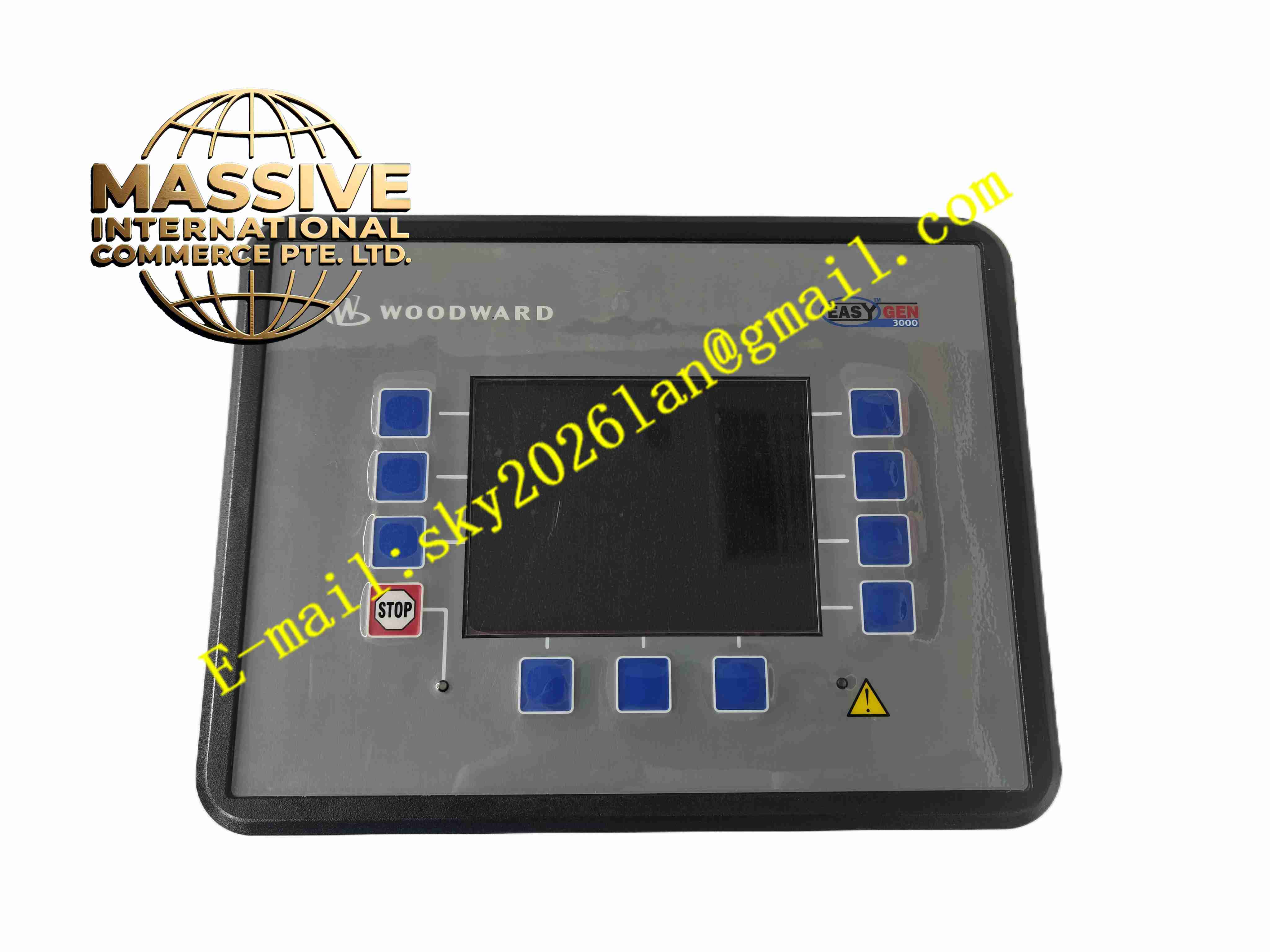
Woodward EASYGEN3500 8440-1936
Technical Specifications:
- Power Supply: 8 to 36V DC
- Voltage Measurement: Direct connect up to 690V AC
- CT Input: 5A current transformer input
- Communication: Ethernet, CAN J1939, RS485
- Analog Inputs: Configurable 0-10V / 4-20mA
- Digital I/O: Configurable digital inputs and relay outputs
- Operating Temperature: -40°C to +70°C
- Storage Temperature: -40°C to +85°C
- Protection Functions: Overvoltage, undervoltage, overfrequency, underfrequency, overcurrent, reverse power
- Synchronization: Automatic synchronizing and soft load transfer
Function Features:
- Automatic mains failure (AMF) control for standby generator application
- Automatic generator synchronization and paralleling with utility or other gensets
- Real kW and kVAR load sharing between parallel generators
- Generator and engine full protection suite with configurable alarm and trip
- Engine control via J1939 CAN bus or analog governor outputs
- Breaker control for generator breaker, mains breaker and bus tie breakers
- Data logging, event recording and trend recording
- easYgen ToolKit software for configuration, monitoring and troubleshooting
- Peak shaving and cogeneration control logic
Application Scenarios:
- Multi-generator standby power plants
- Utility parallel power generation systems
- Combined heat and power cogeneration installations
- Data center and hospital critical backup power systems
- Industrial on-site power generation facilities
Material Composition:
- Housing: Flame retardant plastic front housing, metal rear enclosure
- Main PCB: Multilayer FR4 fiberglass circuit board with conformal coating
- Control Core: High performance industrial microprocessor
- Measurement Components: High precision voltage and current sampling circuits
- Relays: Electromechanical relay outputs for breaker and alarm control
- Terminals: Heavy duty screw terminals for power, CT, VT and I/O wiring
Structural Features:
- Front panel mount design with LCD display and function keys
- Front panel LED indicators for breaker status, alarm and fault
- Separated terminal blocks for voltage, current, digital I/O and communication
- Standard cabinet cutout dimensions for generator control panel installation
- Rear metal shield for electromagnetic interference suppression
Working Principle: The controller measures generator voltage, current and frequency from VT and CT inputs. It monitors engine parameters via J1939 CAN bus. Internal microprocessor executes synchronization logic, closes generator breaker when phase, voltage and frequency match. Load sharing algorithm distributes real and reactive load across parallel gensets. Protection logic continuously monitors electrical parameters and triggers trip relay when values exceed safe thresholds. Event and trend data are stored in non-volatile memory.
Installation Requirements:
- Mount controller on generator control panel front side
- Separate high voltage VT/CT wiring from low voltage digital I/O and communication cables
- Use twisted pair shielded cable for CAN and Ethernet communication
- Follow CT polarity rules carefully during current transformer wiring
- Provide reliable protective grounding for control panel
- Keep away from engine high voltage ignition and large contactors
Usage Notes:
- Complete generator nameplate, CT/VT ratio and protection setpoint configuration with ToolKit software before commissioning
- Perform dead bus and live bus synchronization test before parallel operation
- Backup controller configuration file after commissioning
- Do not exceed CT and VT rated input values
- Disconnect all voltage and current inputs before removing controller
- Periodically check terminal tightness for vibration environment of generator room