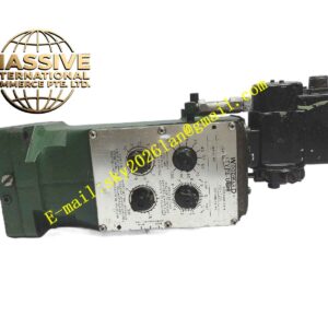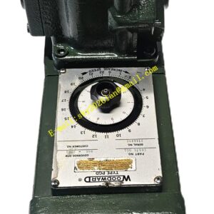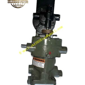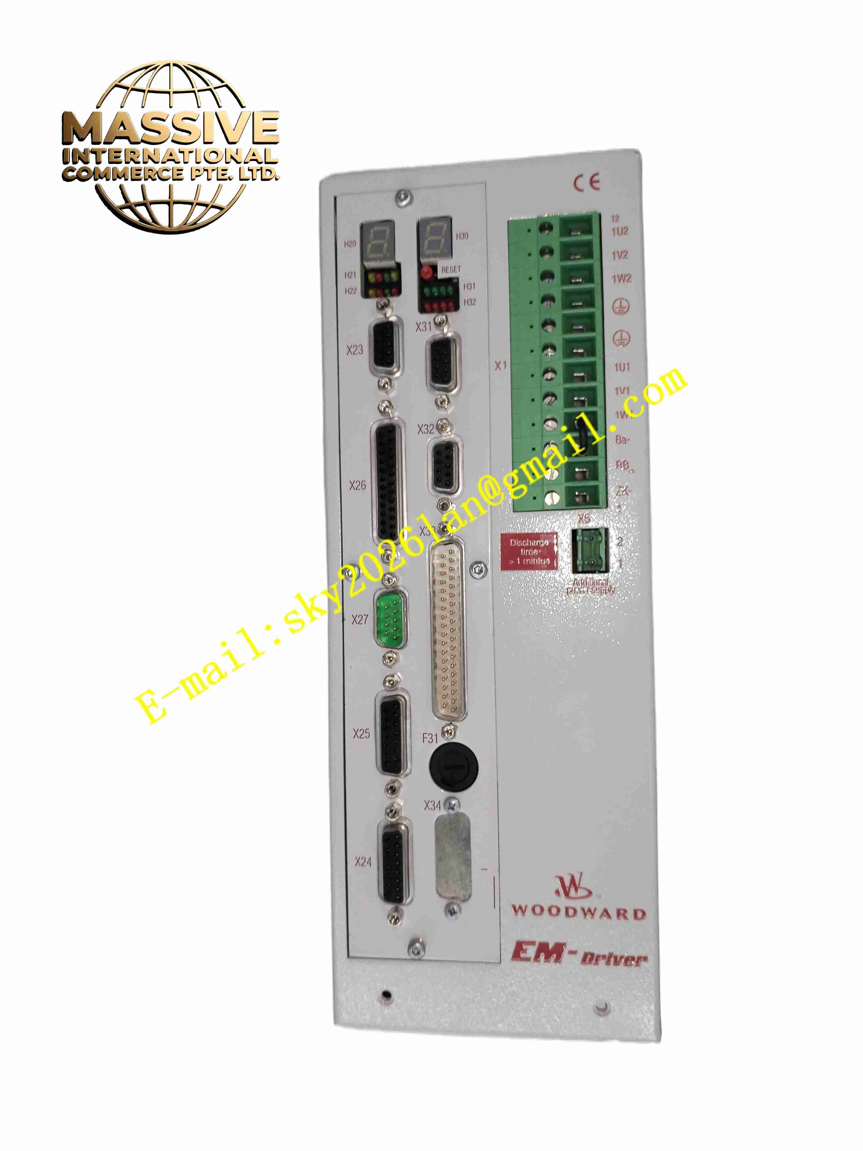
Description
Technical Specifications:
- Output Rotation Stroke: 0° to 40°, no built-in mechanical stops
- Peak Work Output: 133 J (98 ft-lb) within 1 second
- No-load 10–90% Slew Time: 78 ms
- Motor Type: Three-phase brushless AC servo motor
- Position Feedback: High precision resolver
- Power Supply for Driver: 18–32 VDC
- Operating Temperature: -20 °C to +70 °C
- Storage Temperature: -30 °C to +100 °C
- Protection Class: IP65 for actuator housing
- Communication: Serial bus for parameter configuration and diagnostic data
Function Features:
- High stiffness planetary gearbox with low backlash for accurate valve positioning
- Resolver provides continuous rotor position and speed feedback for closed-loop control
- Fully programmable control curve via PC configuration software
- Fast dynamic response for rapid fuel valve adjustment during load change
- Configurable emergency stop input to drive actuator to minimum safety position
- Built-in actuator position monitoring and fault diagnosis
- Support ABS, BV and DNV marine certification for offshore applications
- Low maintenance brushless motor design without carbon brush wear
Application Scenarios:
- Gas turbine fuel gas valve control
- Large reciprocating gas engine fuel control
- Industrial burner and boiler fuel valve actuation
- Offshore oil and gas power generation equipment
- Combined cycle power plant DLE dry low emission gas control valves
Material Composition:
- Actuator Housing: Cast aluminum alloy
- Motor Rotor: Silicon steel laminations with high performance permanent magnets
- Motor Stator: Copper winding with high temperature insulation material
- Gearbox: Alloy steel precision planetary gears
- Shaft: Hardened alloy steel output shaft
- Resolver: Precision magnetic rotary position sensing assembly
- Internal PCB: FR4 circuit board with drive power semiconductors and control chips
Structural Features:
- Compact cylindrical cast aluminum housing
- Integrated brushless servo motor and planetary gearbox inside housing
- Rear mounted resolver assembly for position feedback
- Multi-pin sealed industrial connector for power, feedback and command signal
- External mounting flange for direct coupling to control valve
- Internal slip clutch to protect gearbox against mechanical overload
Working Principle: The drive controller receives position demand signal from turbine or genset main control system. The controller outputs three-phase variable frequency current to brushless servo motor. Motor rotation transfers torque through planetary gear reducer to drive output shaft and valve. Resolver continuously feeds back real-time shaft angle to controller to form closed position loop. Controller adjusts motor current to eliminate position error. Emergency stop signal forces actuator to minimum position for safety protection. Onboard diagnostic circuit monitors motor current, resolver signal and actuator health status.
Installation Requirements:
- Mount actuator rigidly on matched control valve flange
- Align output shaft coupling precisely to eliminate radial and axial misalignment
- Use shielded multi-core cable for command, feedback and power wiring
- Leave sufficient clearance around housing for heat dissipation
- Install cable strain relief to prevent connector mechanical stress
- Connect actuator housing to protective earth per local electrical codes
Usage Notes:
- Complete actuator calibration and stroke setting with Woodward PC configuration software before commissioning
- Verify emergency stop function test before putting into service
- Do not apply mechanical force to rotate output shaft manually during operation
- Prevent water, oil and corrosive gas entering sealed connector
- Disconnect all power supply before opening actuator housing or modifying wiring
- Perform periodic inspection of coupling tightness and cable seal integrity