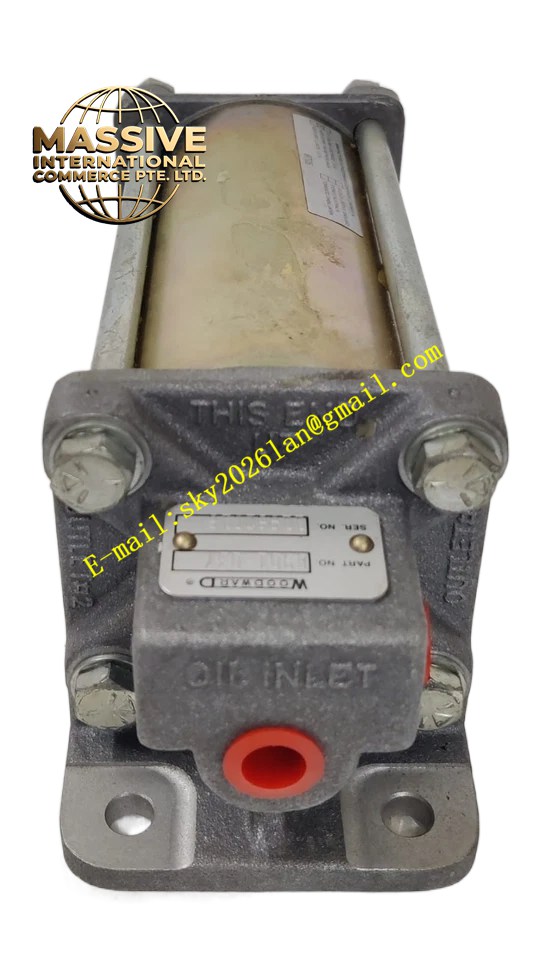
Description
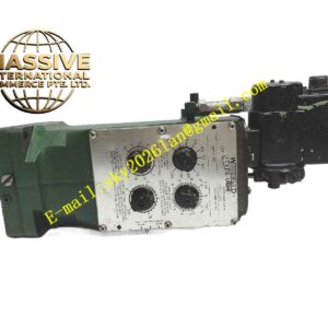
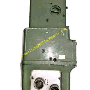
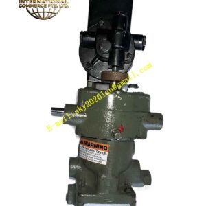
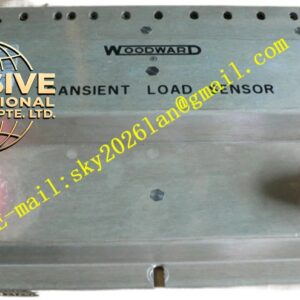
Woodward 8901-037
Technical Specifications
- Product Type: Low-volume, single-cylinder booster servomotor.
- Manual Reference: Covered under Woodward Manual 36684 (Product Manual for Booster Servomotors).
- Regulatory Compliance: Compliant as “SEP” per Article 3.3 to Pressure Equipment Directive 97/23/EC.
- Air Inlet: Features a dedicated air inlet port for connection to the starting-air supply via an air-starting valve.
- Oil Outlets: Equipped with multiple oil outlets (Outlet #1 typically supplies oil to the power piston in the governor).
Functional Features
- Instantaneous Response: Delivers pressurized oil to the governor system precisely when starting air is applied to the engine.
- Check Valve Protection: Incorporates check valves in the oil outlets to prevent oil from flowing back through the outlets into the booster.
- Inlet Isolation: Features a check valve in the oil inlet to prevent oil from flowing from the booster back to the governor sump.
- Spring Return Mechanism: Utilizes internal spring force to return the piston to its original position once starting air is removed.
Application Scenarios
Extensively utilized in conjunction with PG-type governors (such as PGA, PGPL, and PGG) for industrial gas engines, steam turbines, and mechanical drive applications requiring reliable hydraulic starting assistance.
Extensively utilized in conjunction with PG-type governors (such as PGA, PGPL, and PGG) for industrial gas engines, steam turbines, and mechanical drive applications requiring reliable hydraulic starting assistance.
Performance Parameters
- Actuation Phase: Compressed air enters the booster, moving the piston upward to force oil through the outlets to the governor’s pressurized system.
- Reset Phase: Upon removal of starting air, the booster vents to atmosphere, and spring force returns the piston to the ready position.
- Flow Control: The rate of oil flow is regulated by needle valves to control the speed of the power piston movement.
Material Composition
Constructed with heavy-duty industrial-grade materials, including precision-machined steel cylinders, high-performance elastomer O-rings, glide rings for smooth piston travel, and robust internal springs designed for continuous cyclic operation.
Constructed with heavy-duty industrial-grade materials, including precision-machined steel cylinders, high-performance elastomer O-rings, glide rings for smooth piston travel, and robust internal springs designed for continuous cyclic operation.
Structural Characteristics
- Form Factor: Compact single-cylinder design with an outline drawing referenced as Figure 1-3 in the product manual.
- Port Configuration: Includes distinct ports for oil inlet, multiple oil outlets, and starting air inlet.
- Adjustment Mechanisms: Features needle valves for flow control and stroke limit screws for travel adjustment.
Working Principle
When compressed air enters the booster, the internal piston moves upward, forcing oil through the outlets into the governor’s pressurized oil system. This causes the governor’s power piston to move and increase fuel. When starting air is removed, the booster vents to the atmosphere, and an internal spring returns the piston to its original position. Reduced pressure in the booster causes sump oil to flow back into the booster through the inlet check valve, resetting the unit for the next start cycle.
When compressed air enters the booster, the internal piston moves upward, forcing oil through the outlets into the governor’s pressurized oil system. This causes the governor’s power piston to move and increase fuel. When starting air is removed, the booster vents to the atmosphere, and an internal spring returns the piston to its original position. Reduced pressure in the booster causes sump oil to flow back into the booster through the inlet check valve, resetting the unit for the next start cycle.
Installation Requirements
- Connect steel tubing from the governor sump to the oil inlet port on the booster.
- Connect tubing from oil outlet #1 on the booster to the power piston of the governor.
- Connect a line with an air-starting valve from the starting-air supply to the air inlet on the booster.
- Fill the governor with oil to the correct level before initial operation.