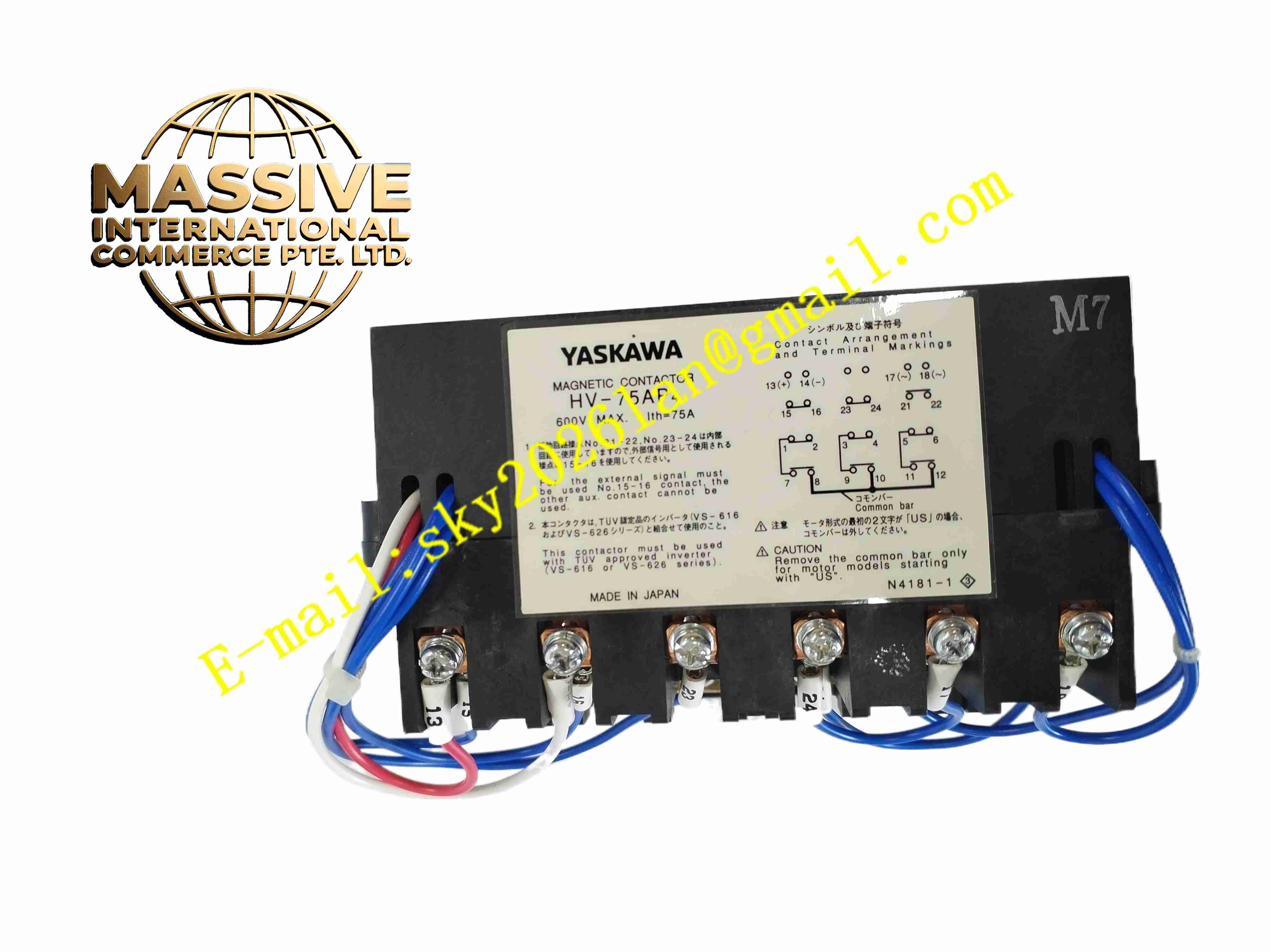
Description
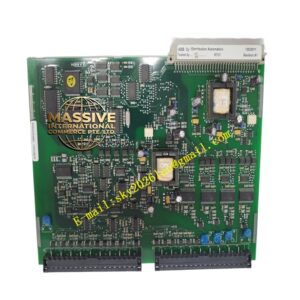
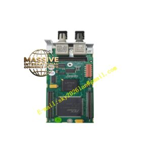
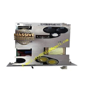
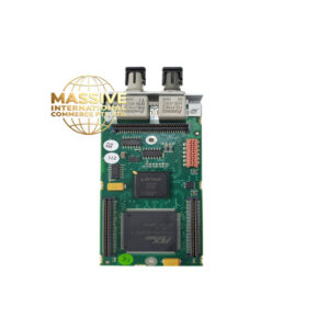
YASKAWA HV-75AP4
Technical Specifications
- Product Type: High voltage AC servo amplifier
- Input Power: 3-phase high voltage AC input
- Rated Output Power: 75 kW
- Control Modes: Torque, speed, position closed-loop control
- Feedback Interface: Incremental encoder, absolute encoder
- Communication Interfaces: Motion bus, analog command, pulse command
- Protection Functions: Overcurrent, overvoltage, undervoltage, overtemperature, encoder fault, overload
- Protection Rating: IP20
- Operating Temperature: 0 °C to +45 °C
- Mounting: Vertical panel mounting inside control cabinet
- Cooling: Forced air fan cooling
Functional Features
- High power three closed-loop control for heavy-duty high voltage AC servo motors.
- Accept multiple command source including pulse train, analog voltage and motion fieldbus command.
- Support incremental and absolute encoder feedback for high precision position measurement.
- Built-in auto-tuning function optimizes servo loop gain for large mechanical loads.
- Comprehensive hardware protection prevents damage under overload, short circuit and overtemperature.
- Fault diagnostic function stores fault codes and operation waveform for troubleshooting.
- Digital I/O channels accept enable, limit and interlock signals and output axis status.
- Front panel LED indicators display power, run and fault status.
- Parameter setting via keypad or Yaskawa PC configuration software.
- Regenerative braking function handles motor deceleration energy for heavy inertial load.
Application Scenarios
- Large CNC machine tool heavy spindle and feed axis drive
- Metal forming heavy press servo axis control
- Large gantry robot joint high power servo drive
- Material test bench high force motion equipment
- Large automated cutting and processing machinery
Material Composition
- Enclosure: Cold rolled steel metal casing with powder coating
- Main PCB: FR4 printed circuit board with conformal coating
- Power components: High voltage IGBT power modules
- Control processor: High speed digital signal processor
- Terminal blocks: High current nickel-plated copper screw terminals
- Cooling components: Axial cooling fan and aluminium heat sink
- Communication connectors: Gold plated D-Sub connectors for encoder feedback
Structural Characteristics
- Vertical rectangular metal cabinet structure for cabinet panel mounting.
- Front panel with keypad, LED indicators and ventilation grilles.
- Internal fan mounted at bottom for upward forced convection cooling.
- Rear high current terminals for three-phase power input and motor power wiring.
- Separate low current connectors for encoder feedback and digital I/O signals.
- Internal isolation barrier separates high voltage power circuit and low voltage signal circuit.
Working Principle Upper motion controller sends motion command to HV-75AP4 servo amplifier. DSP compares command position and actual encoder feedback position, calculates control output through PID algorithm. High voltage IGBT power stage converts three-phase AC input into variable frequency three-phase AC to drive high voltage servo motor. Encoder signal feeds back continuously to close position loop. Digital I/O circuit reads machine limit and emergency stop signals. Built-in protection circuit monitors current, voltage and temperature continuously, cuts off power output immediately when fault condition triggers.
Installation Requirements
- Mount drive vertically inside control cabinet with specified clearance above and below for airflow.
- Use high voltage shielded cable for motor power and encoder feedback wiring.
- Separate motor power cable from low voltage signal and communication cables.
- Complete protective earth connection for drive metal housing.
- Execute motor identification and servo auto-tuning after wiring completion.
- Test limit switch, home switch and emergency stop interlock circuit.
- Verify encoder wiring polarity and count direction before full load test.
Usage Notes
- Do not operate drive with cooling fan failure.
- Keep cabinet air inlet filter clean to prevent dust accumulation blocking airflow.
- Do not connect motor load exceeding drive rated power specification.
- Backup parameter settings before firmware upgrade or configuration modification.
- Disconnect AC input power and discharge DC bus capacitor before opening wiring terminals.
- Use anti-static wristband when handling encoder and control connectors.
- Replace drive immediately when permanent power stage or control hardware fault occurs.