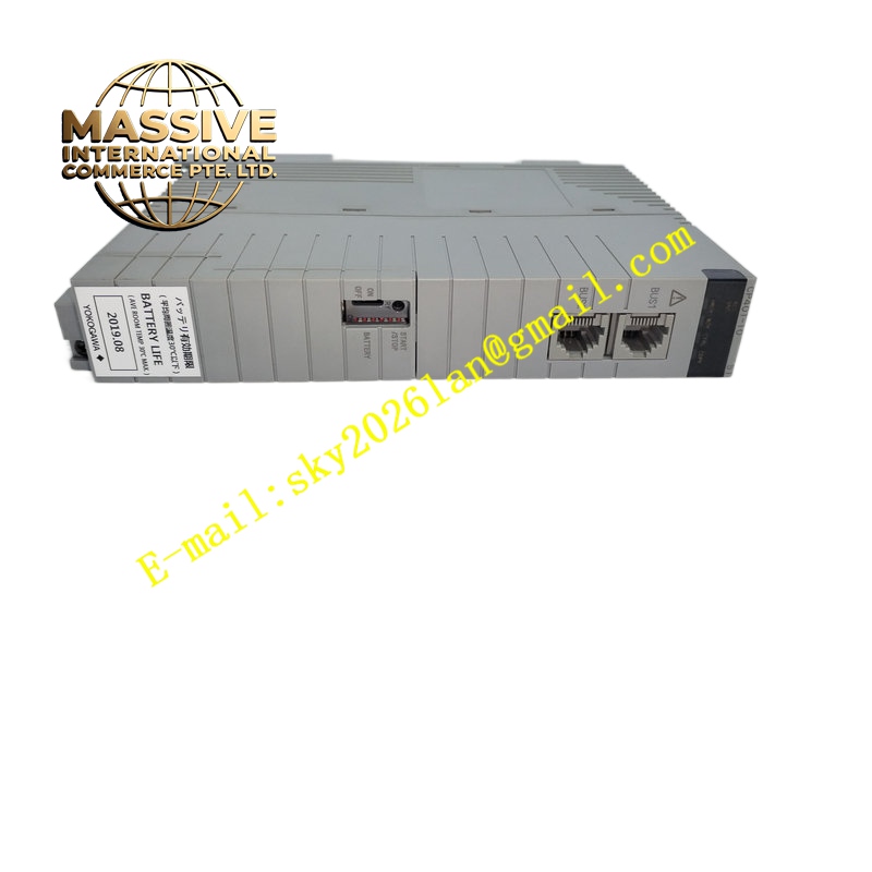
Description
Yokogawa CP401-10
Technical Specifications
Brand: Yokogawa
Product Model: CP401-10
Product Type: Analog Input Module
Application Field: Industrial automation, process control, DCS systems
Input Signal Types: Thermocouples, RTDs, linear voltage (0-10V DC), current (4-20mA), and other standard analog signals
Input Range: Configurable to accommodate various signal amplitudes
Resolution: High-resolution analog-to-digital conversion for accurate measurement
Communication Interfaces: Ethernet, RS-232, RS-485 for data transmission to control systems
Alarm Function: Configurable high/low alarm thresholds for out-of-range detection
Operating Temperature: Industrial-grade temperature range suitable for harsh environments
Certification Standards: Compliant with relevant industrial safety and EMC standards
Functional Features
High-Accuracy Measurement: High-resolution ADC ensures precise conversion of analog signals to digital values
Configurable Input Range: Adaptable to different signal types and amplitudes for versatile application
Real-Time Monitoring: Continuously monitors field signals and reports data to the control system
Alarm Capability: Triggers alerts when signals exceed predefined thresholds for immediate operator awareness
Multi-Protocol Communication: Supports Ethernet, RS-232, and RS-485 for flexible system integration
Industrial Durability: Designed to withstand vibration, temperature fluctuations, and electromagnetic interference
Signal Conditioning: Built-in filtering and isolation to reduce noise and ensure signal integrity
Hot-Swap Capability: Supports replacement without system shutdown in compatible DCS configurations
Self-Diagnostic: Monitors module health and reports faults for proactive maintenance
Application Scenarios
Chemical Processing: Monitoring reactor temperatures, vessel pressures, and flow rates
Oil and Gas: Pipeline pressure and flow measurement, wellhead monitoring
Power Generation: Boiler temperature control, turbine vibration monitoring
Water Treatment: pH level, dissolved oxygen, and flow rate measurement
Pharmaceutical Manufacturing: Sterilization temperature monitoring, bioreactor parameter control
Food and Beverage: Pasteurization temperature control, filling level measurement
Pulp and Paper: Stock consistency measurement, dryer section temperature monitoring
HVAC Systems: Duct temperature and pressure monitoring
Performance Parameters
Input Channels: Multiple analog input channels per module (channel count depends on specific configuration)
Conversion Resolution: High-bit ADC for fine measurement granularity
Sampling Rate: Fast sampling for real-time process monitoring
Accuracy: High-precision measurement with minimal drift over temperature
Isolation Voltage: Galvanic isolation between channels and system ground for safety
Response Time: Millisecond-level response to signal changes
Common-Mode Rejection: High CMRR to reject noise in industrial environments
Update Rate: Configurable data update intervals to the host system
Material Composition
Industrial-grade PCB with high-quality surface-mounted components, precision resistors and capacitors for signal conditioning, isolation transformers for galvanic isolation, metal shielding for EMI protection, gold-plated connectors for reliable contact, flame-retardant housing materials compliant with UL94 standards
Structural Features
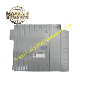
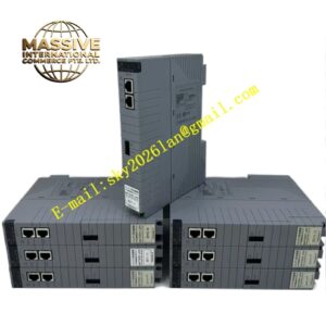
Compact modular form factor for rack or DIN rail mounting, standardized industrial connectors for easy wiring, status LEDs for power, communication, and fault indication, screw terminal or plug-in terminal block for field wiring, robust metal or reinforced plastic housing, thermal management features for continuous operation, keyed connectors to prevent miswiring
Working Principle
The CP401-10 receives analog signals from field sensors such as thermocouples, RTDs, pressure transmitters, or flow meters. These signals pass through input conditioning circuits that provide filtering, amplification, and isolation to protect against noise and voltage spikes. The conditioned analog signal is then fed into a high-resolution analog-to-digital converter (ADC), which transforms it into a digital value proportional to the measured physical quantity. The module’s microprocessor processes this digital data, applies linearization and scaling according to the configured input type and range, and transmits the result to the DCS or PLC via the communication interface. If the measured value exceeds user-defined alarm thresholds, the module triggers an alarm flag. Continuous self-diagnostics monitor the health of the ADC, communication links, and power supply, reporting any anomalies to the control system.
Installation Requirements
Install in a compatible Yokogawa DCS rack or designated mounting location with secure fixation
Ensure proper grounding of the module and rack to minimize electrical noise
Use shielded cables for analog signal wiring, grounding shields at one end only
Verify input type and range configuration matches the connected field instrument
Maintain adequate clearance around the module for ventilation and heat dissipation
Follow Yokogawa wiring diagrams for correct terminal connections
Configure communication parameters (address, baud rate, protocol) before commissioning
Ensure the DCS system recognizes the module during system configuration
Usage Precautions
Disconnect power before installing or removing the module unless hot-swap is supported
Verify signal type and polarity before connecting field instruments to prevent damage
Do not exceed the specified input voltage or current ratings
Use proper cable routing practices to minimize electromagnetic interference
Regularly verify calibration accuracy against known reference standards
Monitor alarm settings to ensure they are appropriate for the process
Replace the module with the exact same model number to ensure compatibility
Keep the module clean and free of dust to maintain proper heat dissipation
Refer to Yokogawa technical documentation for troubleshooting and error code interpretation
Do not attempt internal repairs; return faulty modules to authorized service centers