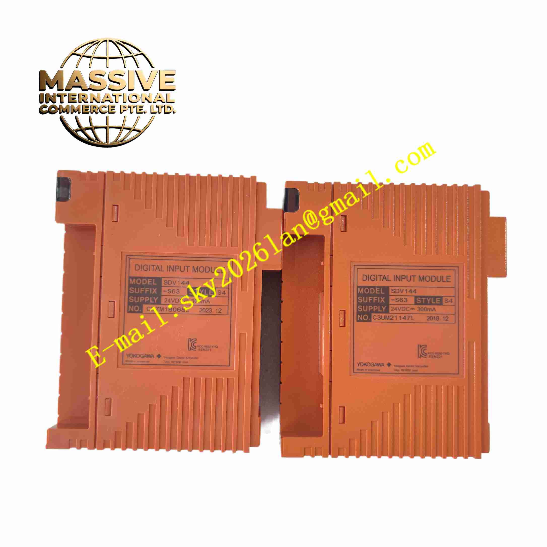
Description
YOKOGAWA SDV144-S63
Technical Specifications Brand: Yokogawa Model: SDV144-S63 Number of Output Channels: 16 digital output channels Output Signal: 24 VDC transistor output Single Channel Rated Current: 0.1 A Insulation: Isolation between internal bus and field channels Operating Temperature: 0°C to +70°C Humidity: 5% to 95% non-condensing Protection Grade: IP20 cabinet installation Mounting: Rack hot pluggable module Communication Interface: Yokogawa DCS backplane bus
Functional Features 16-channel 24 VDC transistor type digital output. Receive control command from CPU module through rack backplane bus. Built-in channel diagnosis function detects short-circuit and open-circuit fault of field wiring. Front panel LED lights indicate power status, running state and each channel output state. Supports hot swapping without system shutdown. Overcurrent protection on each output channel prevents module damage. Supports sequence logic and safety interlock control for field equipment.
Application Scenarios Petrochemical process interlock control, natural gas plant valve actuation, pulp and paper mill sequence control, pharmaceutical batch production line, power plant auxiliary equipment on-off control.
Performance Parameters Rapid response to CPU control commands. Accurate fault detection for field wiring abnormality. High EMC immunity in industrial plant environment. Stable output under long-time continuous operation. Instant overcurrent protection activation on channel overload.
Material Composition Front Panel: Flame retardant black ABS plastic with LED indicators. PCB: FR4 multilayer printed circuit board with conformal coating. Core Components: Bus communication chip, transistor drive chip, optocoupler, surge protection components. Back Connector: Gold plated edge connector for backplane. Field Terminals: Screw clamp plastic terminal block.
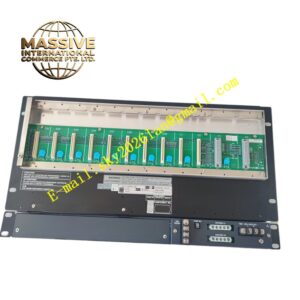
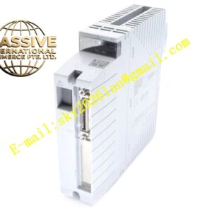
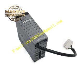
Structural Features Plug-in card structure for DCS rack installation. Rear gold finger connector connects to rack backplane bus. Front panel integrated with LED channel status indicators. Side plastic locking latches fix module in rack slot. Internal galvanic isolation separates field circuit and DCS backplane circuit.
Working Principle DCS CPU transmits digital output command via rack backplane bus to SDV144-S63 module. The module drive chip switches transistor circuit to output 24 VDC signal for field loads. Optocoupler realizes electrical isolation between field side and DCS control bus. Onboard diagnostic circuit monitors channel working condition continuously and reports fault information to DCS operator station.
Installation Requirements Power off rack before inserting module into target slot. Lock side latches after insertion. Connect field load wiring to terminal block. Install freewheeling diode for inductive loads such as solenoid coils. Use shielded twisted pair cable for field wiring. Maintain air circulation in rack cabinet.
Usage Notes Wear anti-static wristband in module replacement operation. Do not exceed single channel rated output current. Check field wiring short circuit before powering module. Avoid condensation inside control cabinet. Backup DCS configuration before module maintenance