Description
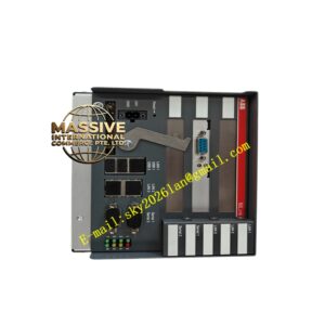
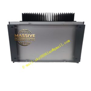
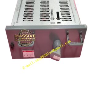
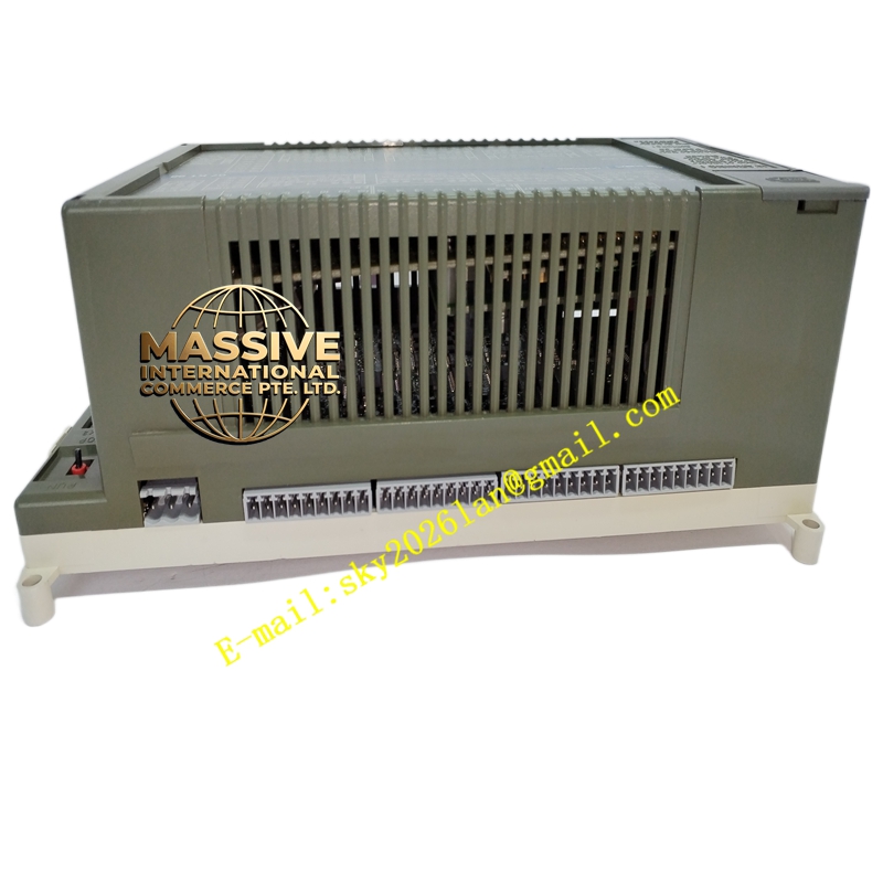
ABB 07KT98B
Technical Specifications
| Parameter | Value |
|---|---|
| Digital Inputs | 24 |
| Digital Transistor Outputs | 16 |
| Digital Inputs/Outputs | 8 (configurable) |
| Analog Inputs | 8 |
| Analog Outputs | 4 |
| I/O Expansion | Up to 992 digital inputs, 992 digital outputs, 224 analog inputs, 224 analog outputs via CS31 system bus (max. 31 remote modules) |
| Serial Interfaces | 2 (for programming and HMI connection) |
| Parallel Interface | 1 (for communication processor connection) |
| Integrated Memory | Flash EPROM: 1MB program + 128kB user data; SRAM: 256kB RETAIN; DRAM: 1MB program + 1MB user data |
| Real-Time Clock Resolution | 1 second |
| High-Speed Counter | 1 hardware counter, 7 configurable operating modes, counting range -32768 to +32767, max. 50 kHz |
| Processing Time | Typ. 0.07 ms/kB program (65% bits, 35% words) |
| Software Timers | Unlimited, delay range 1 ms to 24.8 days |
| Addressable Flags | 8192 bit flags, 8192 word flags, 1024 double word flags |
| Step Chains | 256 |
| Constants | 1440 KW, 384 KD |
| LED Indicators | 60 LEDs total (power, run, error classes, bus status, I/O status) |
| Wiring | Removable screw-type terminal blocks |
| Power Supply Terminals | Max. 1×2.5mm² or 2×1.5mm² |
| Other Terminals | Max. 1×1.5mm² |
| Weight | 1.6 kg |
| Dimensions (W×H×D) | 240×140×85 mm |
| Mounting | DIN rail per DIN EN 50022-35, 15mm deep, plus 4×M4 screws |
Functional Features
- High-Speed Processing: The 0.07 ms/kB typical processing speed ensures rapid response to process changes, critical for time-sensitive control loops.
- Integrated High-Speed Counter: Independent hardware counter operating at up to 50 kHz, functioning autonomously from the user program for fast external signal response. Supports seven distinct operating modes including single-phase, dual-phase, and incremental encoder interfaces.
- Extensive I/O Capacity: Combines 24 digital inputs, 16 digital outputs, 8 configurable digital I/O, 8 analog inputs, and 4 analog outputs on the base unit, expandable to nearly 1000 points via the CS31 system bus.
- Flexible Communication: Two serial interfaces support programming and operator panel connections, while a dedicated parallel interface enables networking with other bus systems through communication processors.
- Robust Memory Architecture: Triple-memory design with Flash EPROM for program storage, battery-backed SRAM for retentive data, and DRAM for active program execution ensures data integrity and fast access.
- Comprehensive Diagnostics: 60 LED indicators provide at-a-glance status monitoring for power supply, program execution, error classification, CS31 bus operation, and individual I/O channel states.
Application Scenarios
- Manufacturing Lines: Central control unit for complex assembly, packaging, and material handling systems.
- Process Industries: Primary controller for batch processing, continuous flow control, and recipe management.
- Building Management: Core automation controller for large commercial building HVAC, lighting, and security systems.
- Infrastructure: Traffic control, water distribution, and wastewater treatment plant automation.
- Machine Building: OEM controller for specialized machinery requiring high I/O density and fast processing.
Installation Requirements
- Mount vertically with terminals positioned above and below for optimal natural convection cooling.
- Maintain minimum 30mm clearance on the right side for SmartMedia card insertion/removal.
- Ensure cable ducts and cabinet materials do not obstruct airflow around the module.
- Interface connectors COM1/COM2 are recessed; account for additional depth if using detachable interface cables with DIN rail mounting.
Operating Precautions
- The configured high-speed counter operating mode is activated only during initialization (power-on, cold start, warm start).
- Disable the counting function when all binary I/O terminals are required for other purposes.
- Use appropriate cable cross-sections per terminal specifications to prevent overheating.
- Battery backup must be maintained for SRAM data retention during power outages.