Description
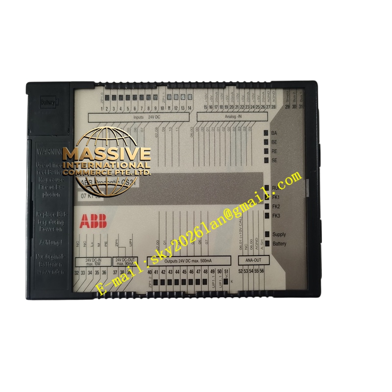
ABB CS3107KT92
- Technical Specifications (typical for this kit class):
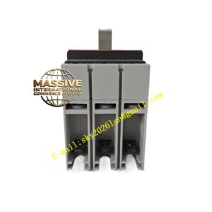
- MCB: 3-pole, C-curve or D-curve, 10–16 A rated (short-circuit breaking capacity 6 kA or 10 kA per IEC 60898/ 60947-2)
- Contactor: 3-pole, AC-3 rating 9 A / 12 A @ 400 V AC; coil voltage per order (24 V DC, 110 V AC, 230 V AC common)
- Thermal Overload Relay: Adjustable current setting (e.g., 7–10 A or 5.5–8 A range), Class 10 trip characteristic, single-phase sensitivity (phase-loss protection)
- Auxiliary Contacts: Overload relay typically provides 1 NO + 1 NC for alarm/trip signaling
- Mounting: 35 mm DIN rail (EN 60715)
- Standards: IEC 60947-4-1, IEC 60898-1, UL 508, CSA
- Functional Features:
- Integrated short-circuit + overload + phase-loss protection in one DIN-rail footprint
- Tool-less or minimal wiring between MCB→Contactor→OLR (often bus-linked in combi-kit)
- Manual ON/OFF via contactor test button; overload trip resets after cooling
- Clear trip class indication (Class 10 standard for motor starting)
- Application Scenarios:
- 3-phase motor control for pumps, fans, compressors up to ≈5.5 kW (400 V)
- Conveyor drive starters in material handling
- HVAC chiller/condenser fan motor starters
- Small process mixer / agitator local control
- Material & Structure:
- MCB: Thermoplastic housing, silver alloy contacts
- Contactor: Silver-cadmium oxide (AgCdO) or AgSnO₂ contacts, AC/DC magnet coil, molded polyester bobbin
- Overload Relay: Bimetallic strip elements with heater coils matched to contactor frame
- All DIN-rail snap-mount; often supplied with bridging bars pre-installed
- Working Principle:
The MCB protects against short circuits by tripping a thermal-magnetic mechanism when current exceeds its magnetic trip threshold. Under normal running overload (e.g., stalled rotor, over-mechanical load), the bimetallic elements in the thermal overload relay heat and deflect, opening the NC contact which interrupts the contactor coil circuit — dropping out the contactor and disconnecting motor power. Phase-loss (one phase open) causes unbalanced heating and also trips the OLR.
- Installation Requirements:
- Mount on 35 mm DIN rail in motor control center or local enclosure
- Verify coil control voltage matches available control supply (24 V DC / 110 V AC / 230 V AC)
- Set thermal overload dial to motor FLA (full load amps) per motor nameplate
- Provide properly sized motor power cables; ensure earthing per local code
- Wire stop/start pushbuttons to contactor A1/A2 via OLR NC contact
- Precautions:
- Do NOT set OLR dial above motor FLA — defeats overload protection
- Verify MCB rating is appropriate — too high = no short-circuit protection for small motors; too low = nuisance trip on inrush
- After a thermal overload trip, allow OLR to cool (several minutes) before resetting
- For frequent start/stop duty (>X times/hour), verify contactor AC-4 rating is adequate — otherwise upsize