Description
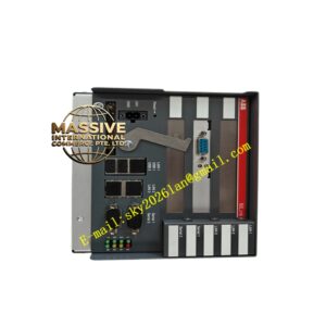
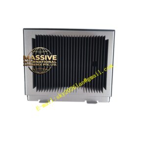
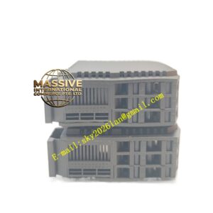
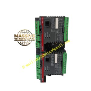
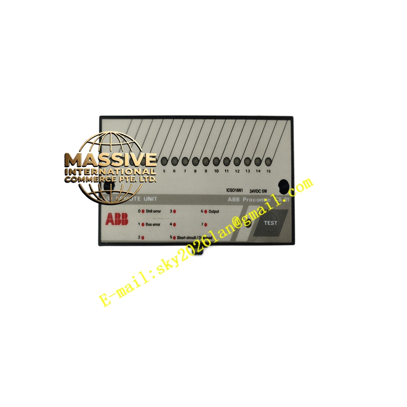
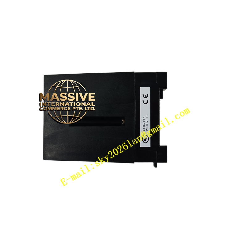
ABB CS31ICSO16N1
- Technical Specifications:
- Output Type: Solid-state sourcing (PNP, supplies +24 V to load)
- Number of Channels: 16 (grouped typically in two groups of 8 with common +24 V per group)
- Nominal Output Voltage: 24 V DC (compatible 20.4–28.8 V DC)
- Output Current: 0.5 A per channel continuous; total max 8 A per group (varies by ambient)
- Turn-on/off Time: <1 ms typical
- Isolation: Optical isolation between logic side and field side (≥1500 V AC test)
- Short-Circuit Protection: Per-channel electronic current limiting with automatic recovery
- Diagnostics: Channel LED (yellow ON = output active), module error LED (red)
- Power Dissipation: Max ≈6 W (fully loaded)
- Mounting: On S800 I/O terminal unit (TU810/TU812 etc.) or CS31 base; 35 mm DIN rail
- Operating Temp.: 0 °C to +60 °C (some –25 °C start-up)
- Functional Features:
- Individual channel status LEDs for rapid troubleshooting
- Built-in inductive load suppression (free-wheeling diode equivalent in output stage)
- Group common terminals simplify field wiring
- Hot-swap capable when I/O station configured for it
- Returns open-load / short-circuit status to controller for alarm generation
- Application Scenarios:
- Controlling 24 V DC solenoid valves on pneumatic/hydraulic actuators
- Driving motor starter contactor coils, indicator beacons, stack lights
- Conveyor divert gates, sorting arm actuators in packaging lines
- Pump start/stop via interposing relay or contactor
- Material & Structure:
- Housing: Flame-retardant polycarbonate/ABS with transparent status window
- Terminals: Screw or spring-cage (depends on TU); gold-plated contacts inside
- Heatsink: Internal copper plane; adequate cabinet ventilation required
- Working Principle:
The module receives a digital output image bit from the controller via the I/O bus. An opto-isolator drives a power MOSFET (PNP source) which connects the channel’s +24 V common to the field device terminal. When the bit is ‘1’, the MOSFET turns on, supplying 24 V DC to the load; when ‘0’, it turns off. Short-circuit is sensed by measuring voltage drop across the MOSFET — if exceeded, the channel latches off and reports a fault until cleared.
- Installation Requirements:
- Plug module into S800 terminal unit ensuring code-key alignment
- Wire +24 V DC supply to group common terminals; verify polarity
- Use appropriate wire gauge (typically 0.5–1.5 mm²) torqued to spec (≈0.5–0.6 N·m)
- Connect field device between output terminal and 0 V (DC return)
- Precautions:
- Total group current must not exceed module rating — observe derating at high ambient (>55 °C)
- For highly inductive AC loads (not directly driven), use interposing relay with snubber
- Do NOT connect output channels to AC voltage — module is DC-only and will be destroyed
- Verify load current does not exceed 0.5 A/channel; fused or protected field supply recommended