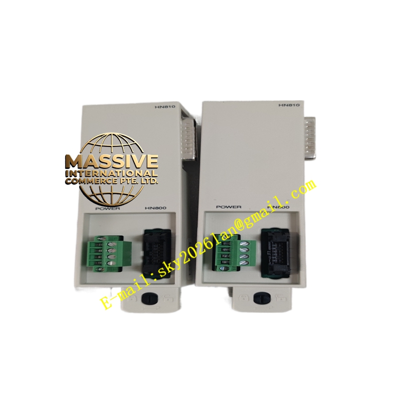
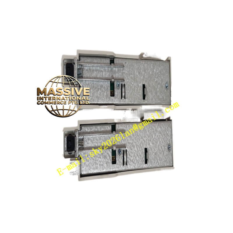
Description
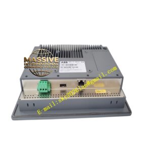
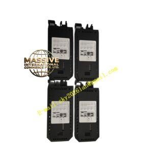
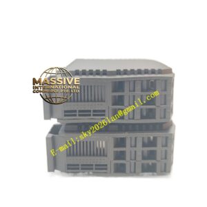
ABB CTB810 (HN800)
- Technical Specifications:
- Function: Signal termination & EMI filtering for HN800 bus and CEX-bus links
- Mounting: Left-side of MB810 base (guided pins + screws)
- Connections: HN800 bus IN/OUT (RJ45 or D-sub per revision), CEX-bus expansion connectors, occasionally service serial port
- Electrical: Passive — signal conditioning/filtering only; backplane-powered (no separate supply)
- Max HN800 Electrical Segment: 30 m (copper); fiber via CRBX01extends to 3 km
- Operating Temp. (cabinet): –20 °C to +55 °C
- Protection: On-board TVS diodes for ESD/surge suppression on bus lines
- Functional Features:
- Clean separation of controller internal bus from field wiring
- Labeled pinouts for HN800 A/B buses and CEX expansion
- Facilitates hot-base swap — controller unplugged with CTB810 remaining cabled
- LED indicators (on controller/base) reflect bus status, not on CTB810 itself
- Application Scenarios:
- Mandatory component in Symphony Plus HPC800 controller assemblies
- Interfaces local I/O racks (SD Series) via HN800 copper or fiber (with CRBX01)
- Used in power, pulp & paper, oil & gas DCS cabinets
- Material & Structure:
- PCB: FR4 with gold-plated edge fingers engaging controller base
- Connectors: Insulation-displacement or screw-terminal blocks; RJ45 or DB9 for
- Mounting hardware: Captive screws + guide pins
- Working Principle:
The CTB810 passively routes differential bus signals from the controller backplane to the external cabling. It includes RC filtering / ferrite beads to suppress high-frequency noise and ESD protection diodes on signal pairs. No signal regeneration or protocol processing occurs — it is purely a physical-layer interface.
- Installation Requirements:
- Align CTB810 with left-side guide pins of MB810 base; press in and secure with two captive screws
- Connect bus cables observing A/B pair and shield grounding (shield typically grounded at controller end only)
- Verify all connections are seated before powering controller
- For fiber extension, connect CRBX01 to ports on CTB810
- Precautions:
- Handle by edges — avoid touching gold edge-fingers
- Do NOT attempt to power separately — damage may occur if forced
- Ensure bus is properly terminated (termination resistor plug or DIP-switch on last node) — missing termination causes reflection errors
- When replacing controller (HPC800), can remain cabled — reduce strain on attached wires during removal