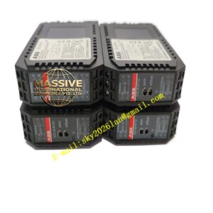
Description
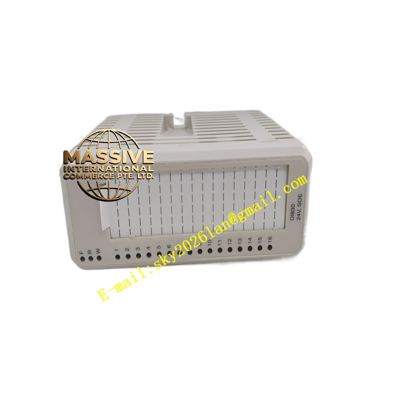
ABB DI830
- Technical Specifications:
- Input Voltage: 24 V DC (range 18–30 V DC; “0” = –30…+5 V, “1” = 11–30 V)
- Number of Channels: 8 channels (2 groups of 4) or 16 channels variant per configuration; typical DI830 = 8 ch with SOE
- Input Type: Current sinking (field device sinks current to 0 V)
- Input Impedance: ≈3.1 kΩ
- Input Current: ≈7 mA @ 24 V DC per channel
- SOE Resolution: 1 ms; event buffer up to 512 × 16 events
- Filter Time: Software-selectable 0–127 ms (digital debounce)
- Isolation: Group-wise isolated from ModuleBus (500 V AC dielectric test, 50 V rated insulation)
- Power Dissipation: Typ. 1.8 W (fully loaded)
- ModuleBus Current: +5 V typ. 80 mA, max 100 mA
- Max Field Cable Length: 600 m (shielded recommended)
- Operating Temp.: 0 °C to +55 °C (for compact MTU vertical mount max +40 °C)
- Enclosure: IP20, flame-retardant ABS/PC
- Compatible MTUs: TU810, TU812, TU814, TU830, TU833, TU842, TU843, TU852
- Certifications: CE, UL/cUL, ATEX / IECEx Zone 2, marine (ABS, BV, DNV, LR), SIL2 capable in system context
- Functional Features:
- Sequence of Events (SOE) with 1 ms time tagging for trip/alarm analysis
- Shutter filter to suppress spurious transitions (contact bounce / EMI)
- Per-channel status LED (green = input active)
- Module Run / Fault / Warning LEDs
- Process voltage supervision per group
- Conformal coating (G3 per ISA-S71.04) standard on S800 I/O
- Application Scenarios:
- Turbine / boiler auxiliary equipment limit-switch monitoring with event time-stamping
- Process plant discrete status feedback (pump running, valve open/closed)
- Safety-related status monitoring when integrated into SIL-rated system architecture
- Retrofit of legacy Advant S500 I/O in extended plants
- Material & Structure:
- Housing: Gray flame-retardant polycarbonate/ABS with transparent status window
- PCB: Industrial-grade FR4 with G3 conformal coat
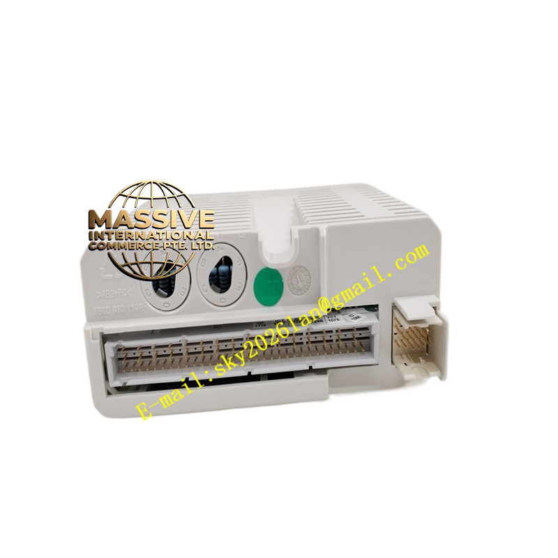
- Connectors: Engages S800 MTU terminal unit (screw or spring-cage field terminals on TU)
- Keying: Physical key-code on module base prevents mismating with incompatible MTU
- Working Principle:
Each input channel senses the voltage between the field-input terminal and the 0 V reference. When the field device pulls the input to +24 V (within “1” range), an opto-isolator is activated and the channel bit is set in the I/O image table. The module’s ASIC time-stamps state changes meeting the filter criteria and queues SOE records for retrieval by the controller. Process voltage on each group is monitored; loss triggers a diagnostic warning.
- Installation Requirements:
- Insert DI830 into matching S800 terminal unit (MTU) ensuring mechanical key alignment
- Wire field sensors between +24 V DC process supply and input terminal; return to 0 V common
- Connect shield of signal cable to ground at one end (typically cabinet earth)
- Download I/O configuration via Control Builder / Freelance Engineering Workbench
- Precautions:
- Do NOT apply >30 V DC to input terminals — may damage input stage
- Verify sinking (NPN) sensor wiring — sourcing (PNP) sensors require DI814 or DI818
- For accurate SOE, ensure controller time synchronization (NTP/SNTP or IRIG-B) is configured
- Keep field wiring separated from high-power AC / VFD cables