Description
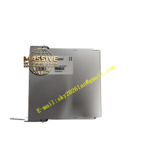
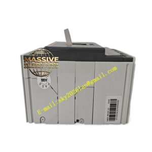
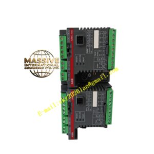
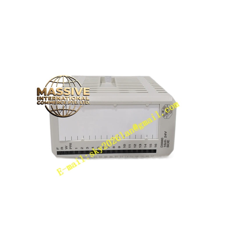
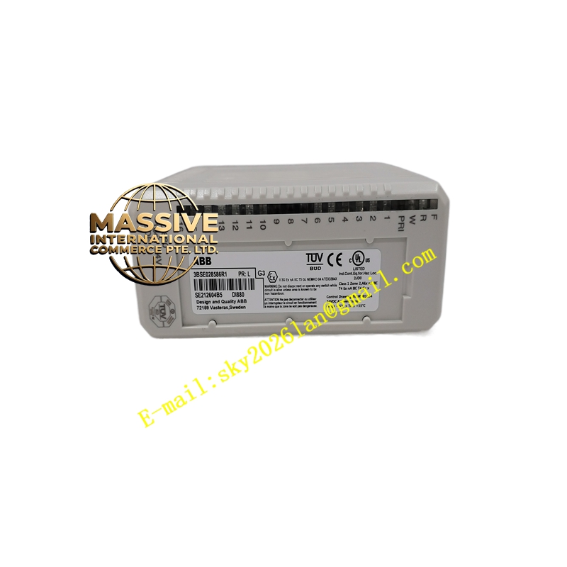
ABB DI880
- Technical Specifications:
- Input Voltage: 24 V DC (range 18–30 V DC; “0” = –30…+5 V, “1” = 11–30 V)
- Channels: 16, one group (galvanically isolated from ModuleBus)
- Input Impedance: 3.1 kΩ
- Input Current: ≈7 mA @ 24 V DC per channel
- Sensor Power: One current-limited 24 V DC sensor supply output per channel (typ. 25 mA limit)
- SOE: 1 ms resolution, up to 512 × 16 event buffer, shutter filter configurable
- Isolation: Group isolated from backplane (500 V AC test, 50 V rated)
- Redundancy: Supports 1oo2 (two-out-of-two) redundant pairing with second DI880
- Safety Integrity: SIL3 per IEC 61508, Category 4 per EN 954-1/ EN ISO 13849-1
- Power Dissipation: Typ. 2.4 W (fully loaded)
- ModuleBus Current: +5 V typ. 125 mA, max 150 mA; +24 V ext. max 527 mA (incl. sensor power)
- Max Field Cable Length: 600 m
- Operating Temp.: 0 °C to +55 °C (compact MTU vertical: max +40 °C)
- Compatible MTUs: TU810V1, TU812V1, TU814V1, TU830V1, TU833, TU842, TU843, TU852
- Certifications: CE, UL 61010, ATEX / IECEx Zone 2, cULus, SIL3, marine (ABS, BV, DNV, LR)
- Functional Features:
- SIL3 certified for use in safety loops (ESD pushbutton, fire/gas detector status, etc.)
- Built-in self-test and channel diagnostics reported to controller
- Per-channel sensor excitation simplifies 2-wire proximity switch wiring
- Supports redundant hot-standby pairing — automatic switchover on failure
- SOE with time synchronization for root-cause analysis of process trips
- Application Scenarios:
- Emergency Shutdown (ESD) pushbutton / pull-cord status monitoring in SIS
- Fire & Gas (F&G) detector discrete alarm inputs in oil & gas / petrochemical plants
- Safety gate / interlock position confirmation in high-risk machinery
- High-integrity turbine protective trip-status inputs
- Material & Structure / Working Principle / Installation / Precautions: Same family as DI830 but note:
- Redundancy Precaution: When used redundantly, both modules must be identically configured and connected to the same field devices via isolation diodes or wiring per ABB redundancy diagram — improper wiring invalidates SIL claim.
- Sensor Power: Each channel’s sensor supply is current-limited — do NOT parallel multiple channels’ sensor supplies to power a single device.
- Periodic Proof Test: SIL loop requires proof-test interval per safety manual— document DI880 function test in SIS proof-test record.