Description
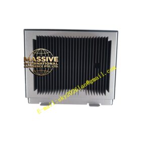
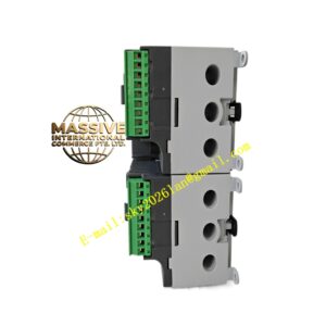
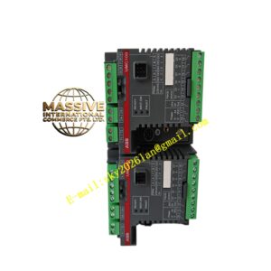
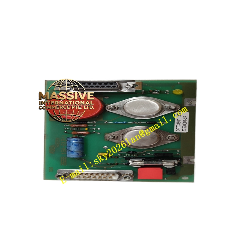
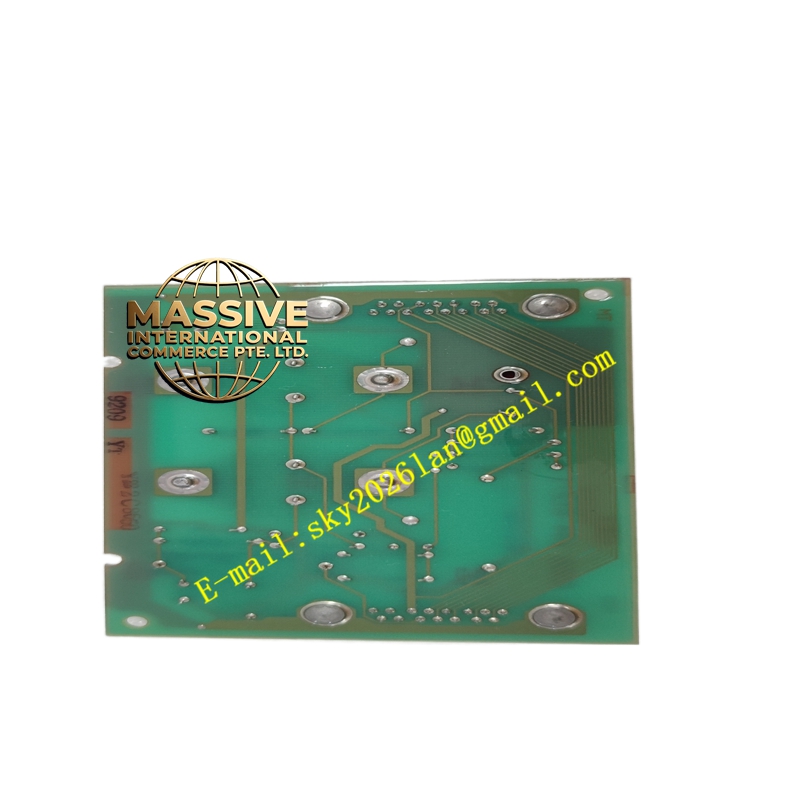
ABB DSTA131
- Technical Specifications:
- Function: Passive signal termination — routes field wires to module pins via gold-plated edge connector
- Terminals: Screw terminals, 0.2–2.5 mm² wire size; pitch 5.08 mm or 7.62 mm
- Channels: Matches module — typically 8 or 16 analog channels + commons / compensation terminals
- Built-in Features: CJC sensor (on TC versions — Pt100 CJC element on board); shunt resistor options (for special current inputs — usually not on std voltage/current AI which has internal shunt)
- Isolation: Signal wires referenced to module common; isolation to earth provided by module’s internal A/D isolation
- Mounting: Snaps onto 35 mm DIN rail; mates mechanically with S100 analog I/O module above
- Material: Flame-retardant polyamide (PA66) with tin-plated brass terminals; aluminum heat-spreader under CJC area
- Operating Temp.: –20 °C to +60 °C
- Dimensions: ≈100 × 120 × 45 mm (W × H × D) depending on channel count
- Functional Features:
- Test jacks / test points per channel for measuring loop current/voltage with multimeter without breaking circuit
- Clearly labeled terminal numbering matching ABB S100 I/O wiring diagrams
- CJC sensor (on TC version) feeds reference temperature to AI module for accurate TC linearization
- Removable terminal block (on some variants) for easy module replacement without rewiring
- Application Scenarios:
- Terminating 4–20 mA 2-wire transmitter loops to DSSA165 analog input module
- Connecting Pt100 RTDs (3-wire) or thermocouples with CJC to S100 AI module
- Providing local test access for calibration / troubleshooting analog loops
- Material & Structure / Working Principle / Installation / Precautions:
- Mount DSTA131 on DIN rail, plug analog module (DSSA165 etc.) directly onto it — engage both mechanical latches
- For 4–20 mA: + from transmitter to Ix(+), – to Ix(–) / common; ensure loop powered correctly
- For TC: use compensating / extension wire type matching TC; connect +/– correctly; CJC must not be covered by warm air streams
- For RTD 3-wire: connect leads per diagram — two to one terminal (common), one to sense terminal
- Do NOT apply >30 V between any input terminal and common — may damage module plugged above
- Keep thermocouple wiring separated from AC power / VFD cables to avoid induced noise