Description
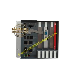
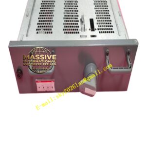
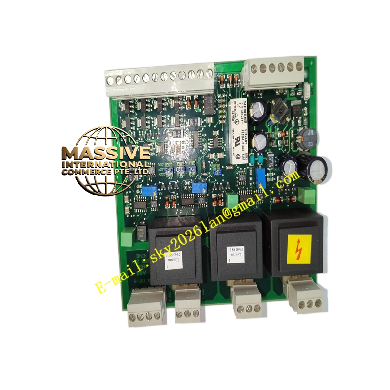
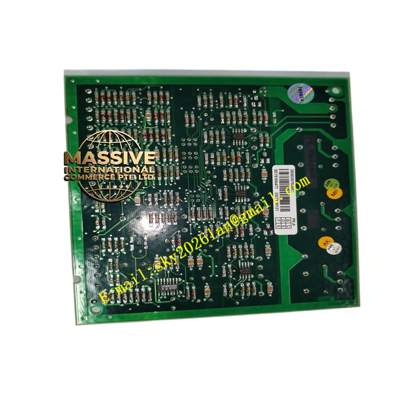
ABB DSTYW121
- Technical Specifications (typical 4-ch 4–20 mA AO):
- Output Channels: 4 (isolated) or 8 (group-isolated)
- Output Types: 4–20 mA (active, max load 500–750 Ω @ 24 V loop supply), 0–10 V, ±10 V (selectable per channel group in config)
- Resolution: 12-bit or 14-bit D/A converter
- Accuracy: ±0.2 % of full scale
- Update Time: ≈200 ms per channel (full scan) or faster with enhanced FW
- Load Drive Capability: ≤500 Ω @ 24 V external loop supply (module may supply internal loop power or require external loop PSU — check version)
- Isolation: Channel-to-backplane 500 V DC; channel-to-channel within group common (or individually isolated in iso-version)
- Power: From S100 backplane + external loop supply if 4–20 mA active loop powered externally
- Indicators: Module Run / Error LED; per-channel activity on some versions
- Operating Temp.: 0 °C to +60 °C
- Mounting: Plugs onto AO termination base (DSTA…series) in S100 rack
- Certifications: CE, UL
- Functional Features:
- Open-circuit detection on current outputs (reports fault if loop broken)
- Configurable output behavior on comm loss / watchdog — hold last value, go to preset safe value (e.g., 4 mA or 0 V), or force to defined alarm state
- Scaling in controller to engineering units (0–100 %, 0–xxx °C equivalent)
- Test points on termination base for measuring loop current without breaking wire
- Application Scenarios:
- Speed setpoint to ABB / third-party VFD (4–20 mA)
- Position setpoint to control valve positioner (4–20 mA)
- Recorder / trend pen drive (0–10 V or 4–20 mA)
- Retrofit of legacy S100 analog control loops in process plants
- Material & Structure / Working Principle / Installation / Precautions:
- Mount termination base on DIN rail, plug AO module onto it
- For 4–20 mA active output: connect + terminal to transmitter/sensor +, – to common/return; ensure loop is closed (2-wire analog output = sourcing from module or external PSU — verify diagram)
- For externally powered loops: connect external 24 V DC to loop supply terminals on termination base
- In controller, configure AO range, failure action, and scaling
- Verify load resistance < max drive capability — long loops with multiple receivers may exceed 500–750 Ω
- Do NOT short 4–20 mA output terminals while powered — brief short tolerated but avoid; open-circuit is detectable and reports fault
- For voltage output (0–10 V) ensure minimum load ≥1 kΩ to maintain accuracy