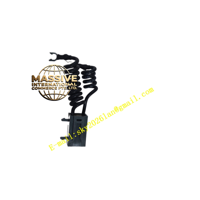
Description
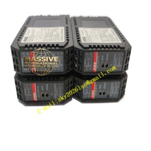
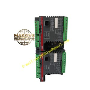
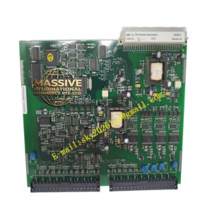
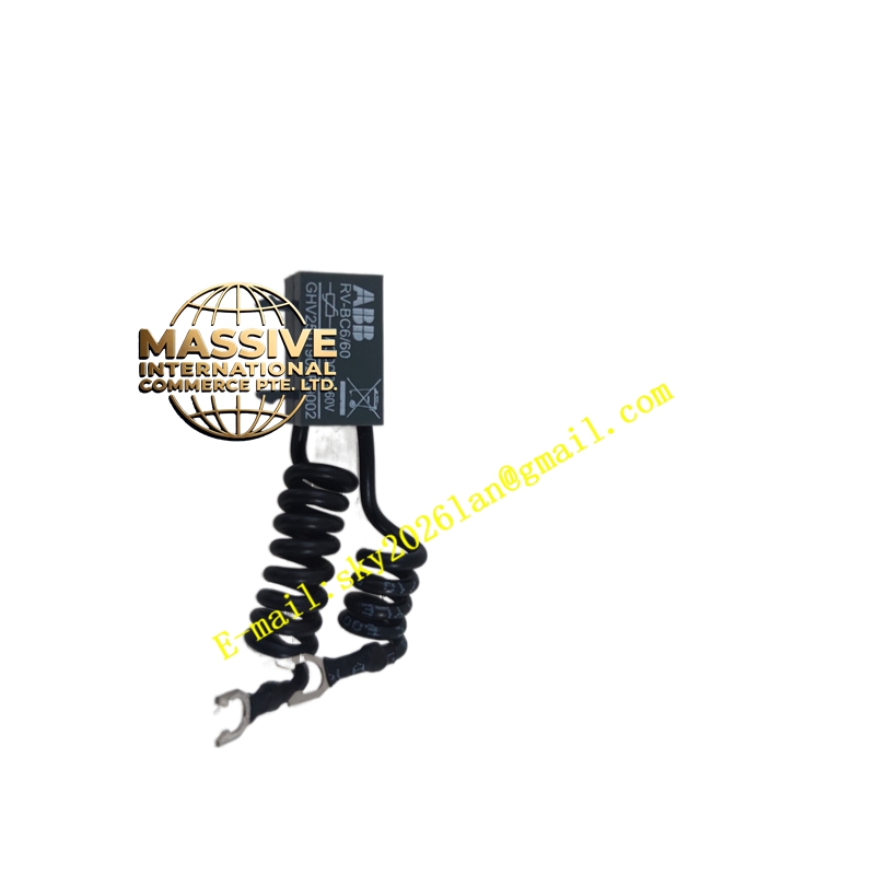
ABB GHV2501902R0002
- Technical Specifications (typical for turbine interface board):
- Supply: 24 V DC or ±15 V DC from backplane (model-dependent)
- Inputs: Discrete 24 V DC status / contact inputs; analog tach / LVDT signals (some versions)
- Outputs: Relay drive, SSR trigger, or opto-coupled status to controller
- Isolation: Optical isolators between field/sensor side and logic (≥1 kV test)
- Connectors: PCB edge-finger (backplane) + header/JST for local I/O
- Operating Temp.: –20 °C to +60 °C (industrial grade)
- PCB: FR4, solder-mask, silk-screen; conformal coat (G3 per ISA-S71.04on turbine-rated boards)
- Mounting: Plug-in to dedicated slot in turbine I/O rack or gate-drive chassis
- Functional Features:
- Signal conditioning (filtering, debounce, scaling) for turbine protection inputs
- Watchdog / heartbeat monitoring from main processor
- LED per channel or per function for field diagnostics
- Compatible with ABB turbine protection logic (overspeed, vibration, flame failure)
- Application Scenarios:
- Gas turbine Mark V / Mark VI control cabinet — protection/interface card
- Medium-voltage drive — IGCT gate-unit interface / feedback board
- Generator breaker control interface in excitation / protection cubicle
- Material & Structure / Working Principle / Installation / Precautions:
- Install in designated slot; ensure backplane connector is clean
- Verify jumper/DIP-switch settings match system configuration (consult turbine commissioning docs)
- Handle by edges; use ESD wrist strap
- Do NOT power board outside its designated rack — incorrect backplane voltage can destroy components