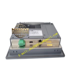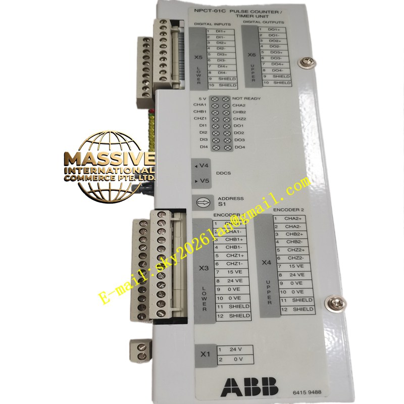
Description
ABB NPCT-01C
- Technical Specifications:
- Termination Resistor: 95 Ω ±1 % (engage via DIP or jumper when last S100 node)
- Time Sync Input (opt.):
- IRIG-B (DC 61374 DCLS): 1 V p-p or TTL level — BNC or screw terminal
- NTP: Via Ethernet (if NPCT-01C version has RJ45 — some do; basic NPCT-01C has IRIG-B only)
- Indicators: Pwr (green), S100 Active (yellow), Terminator On (green), Sync Lock (green if time locked)
- Mounting: Advant 450 CPU rack dedicated terminator slot OR DIN rail (with S100 bus cable to first S100 rack)
- Operating Temp.: 0 °C to +55 °C
- Power: From Advant rack backplane (5 V DC) or external 24 V DC (model dep.)
- Functional Features / Application / Material / Structure / Working Principle / Installation / Precautions:
- Used in EVERY S100 I/O cluster — must be installed at the physically last S100 module/rack (or if rack is intermediate, disable termination & place 95 Ω plug at true last node)
- If controller participates in plant-wide SOE: connect IRIG-B from GPSclock → NPCT-01C BNC → controller RTC locks → all events time-stamped to UTC ±1 ms
- Installation:
- Insert NPCT-01C into Advant rack terminator slot OR DIN-mount near first rack & connect bus cable from SPCJ4D34 / CI520A to NPCT-01C “IN” then “OUT” to first TU (if in-line) — or if is at last rack simply land bus there & enable terminator jumper
- If used as pure terminator (no time sync): enable 95 Ω jumper (slide to ON if this is last node)
- If time sync: connect IRIG-B BNC (shield to ground) → verify Sync Lock LED after power-up
- Precaution: Forgetting to enable termination (or enabling at wrong node) → bus CRC errors / module dropouts. If is NOT the last device (e.g., another rack daisy-chained after it) → keep terminator jumper OFF; place 95 Ω plug at true last rack. Verify bus voltage (≈5 V DC between logic + / GND) after power-up.