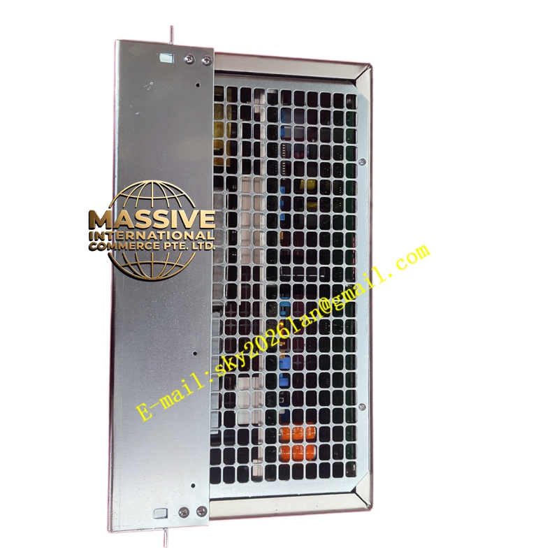
Description
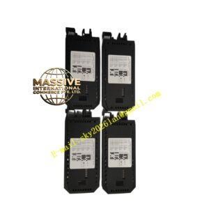
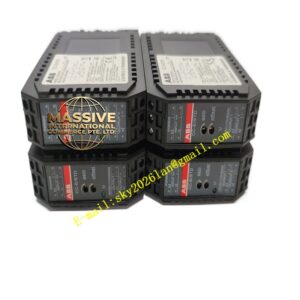
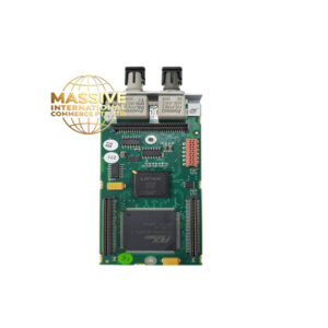
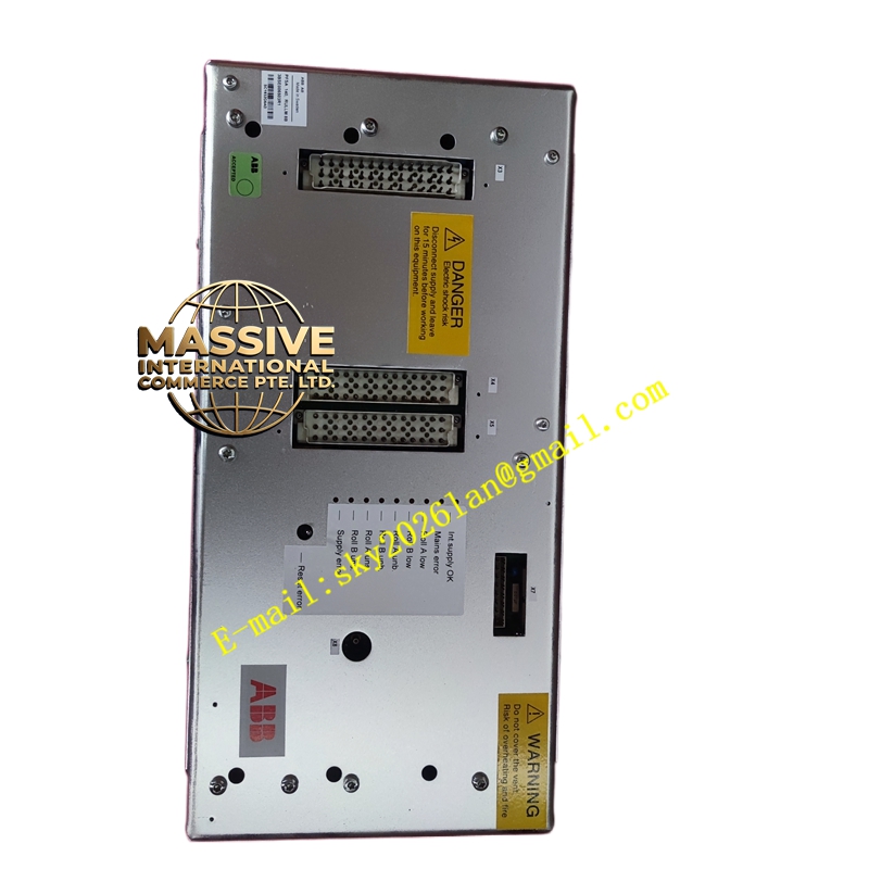
ABB PFSA140 (3BSE006503R1)
- Technical Specifications:
- Input Types Accepted:
- Pressductor® sensor (via PFSA-specific 6-wire cable — excitation + signal pair)
- Strain-gauge bridge: 2 mV/V nom., 350 Ω (other ranges jumper-selectable 1.5–3 mV/V)
- Excitation: 10 V DC (strain-gauge mode) or Pressductor proprietary AC excitation (for noise immunity)
- Number of Channels: 1 (some PFSA140 variants = 2 ch — check label)
- Output Signals: 0/4–20 mA (into ≤500 Ω); 0–10 V (≥10 kΩ load) — jumper / DIP selectable
- Zero Adjustment: ±20 % FS via front trim pot or push-button auto-zero (with sensor mounted, zero-load condition)
- Span Adjustment: ±20 % FS via trim pot
- Filter: Selectable damping (none / 0.1 s / 0.3 s / 1 s / 3 s) to smooth noisy tension signal — important on oscillating lines
- Sensor Break Detection: <2 mA or >22 mA flag (on 4–20 mA range) — drive can detect as wire-break alarm
- Power Supply: 100–240 V AC 50/60 Hz or 24 V DC (model dependent)
- Indicators: Power (green), Signal Active (green), Sensor Fault (red), Overrange (amber)
- Mounting: 35 mm DIN rail (EN 60715)
- Dimensions: ≈45 mm (W) × 110 mm (H) × 120 mm (D)
- Operating Temp.: –10 °C to +55 °C
- Certifications: CE, UL, cUL (some versions ATEX for associated apparatus in IS barrier loop)
- Input Types Accepted:
- Functional Features:
- Auto-zero button — with roll installed & web off, press → sets current reading as zero (compensates for roll weight / dead load)
- Damping selectable to stabilize tension readout on high-speed lines
- Test mode — injects fixed % of span for loop check without applying load
- Compatible with ABB tension control loops (feed to drive PID or to DCS/PLC analog input)
- Can be used stand-alone or as part of ABB tension control system (with PFEA, PFVC, etc.)
- Application Scenarios:
- Conditioning PFRL101C PillowBlock output for unwind/rewind tension display & control
- Converting strain-gauge press/nozzle load cell signal to 4–20 mA for PLC/DCS
- Retrofit of older mechanical tension indicator — replace with PFSA140 + PFRL/PFTL sensor
- Material & Structure / Working Principle / Installation / Precautions:
- DIN-rail mount in panel near drive / control cabinet; keep away from VFD power section
- Connect sensor cable to marked terminals (Ex+, Ex–, Sig+, Sig– for SG; multi-pin circular for Pressductor)
- Connect 24 V DC or 100–240 V AC power; connect output to analog input of drive/PLC
- Power up → perform auto-zero with no tension on roll → set span if needed (usually factory-calibrated to sensor’s rated load — only fine-tune if system ratio differs)
- Select damping appropriate to line speed — too little → jitter; too much → slow response to real tension changes
- Precautions:
- Verify sensor type selected via DIP switches (Pressductor vs Strain-Gauge) — wrong selection = no meaningful output or gross error
- Shield must be connected ONLY at PFSA140 end (drain wire to ground terminal) — floating at sensor end to avoid ground loops (unless Pressductor cable specifies otherwise — follow cable diagram)
- Do NOT short excitation terminals — damages internal supply
- For IS barrier applications: PFSA140 must be installed in safe area; barrier (MTL / P+F) between PFSA140 and IS field sensor — order IS-compatible version & barrier kit