Description
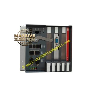
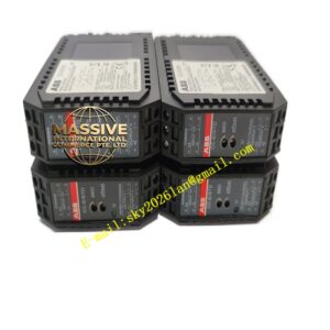
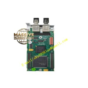
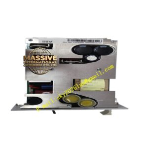
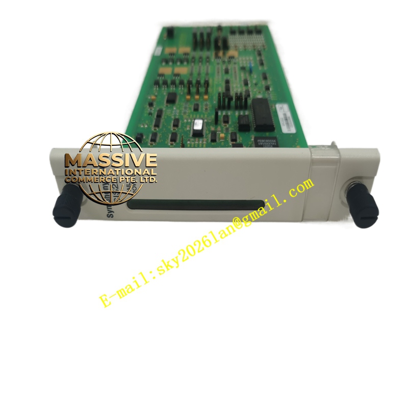
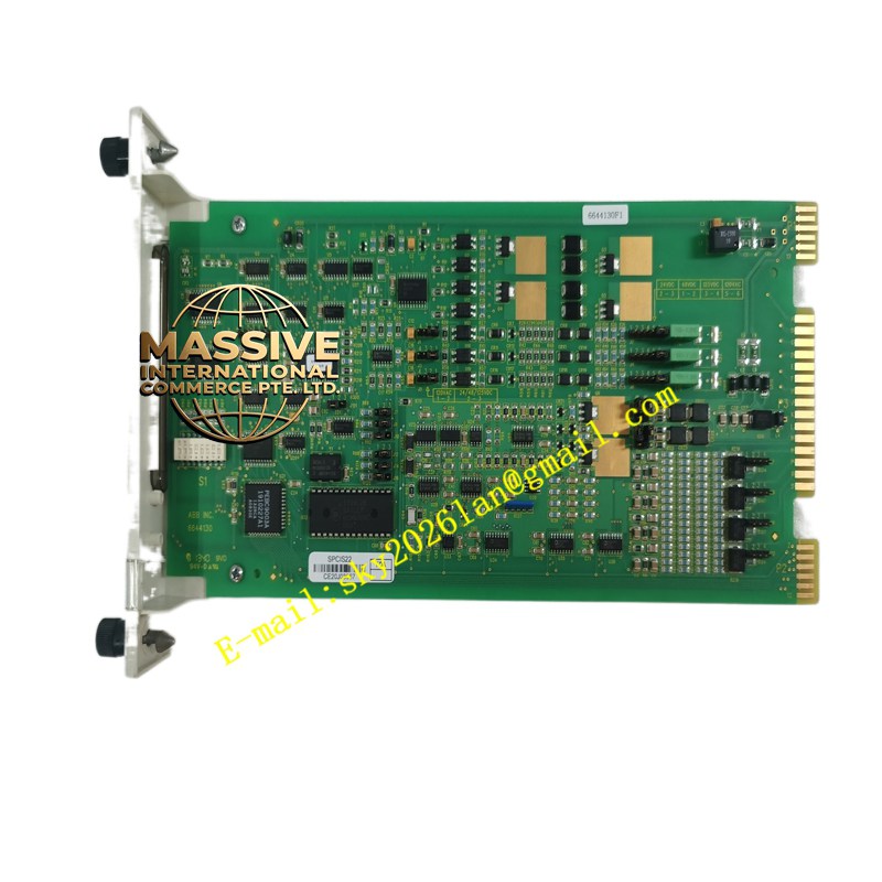
ABB SPCIS22
- Technical Specifications (typical for a CIS22 variant — verify exact by module label; common mix e.g., 16 DI 24 V DC + 8 DO Relay 2 A + 2 AI 0–10 V / 4–20 mA):
- Digital Inputs: 16 × 24 V DC (sinking/sourcing selectable via jumper or parameter), wetting voltage provided, debounce filter
- Digital Outputs: 8 × Relay (SPDT or SPST-NO), 2 A @ 250 V AC / 30 V DC (resistive); short-circuit protected (some versions electronic fusing)
- Analog Inputs (if present): 2–4 × 0–10 V / 4–20 mA / ±10 V — 12-bit A/D, open-sensor detect
- Bus Interface: Integrated S100 bus (daisy-chain to next CIS module or to CI520A interface)
- Power: 24 V DC from S100 bus (via terminator / PSU module e.g., SPU01)
- Indicators: Run (green), Err (red), DI Active LEDs per group, DO Energized LEDs
- Mounting: On S100 termination unit (TA563 / TA566 etc.) — DIN rail
- Operating Temp.: 0 °C to +55 °C
- Certifications: CE, UL, cUL, marine (DNV etc.)
- Functional Features:
- Hot-swappable (with S100 bus active & controller configured for it)
- Module diagnostics (wire break on DI with wetting — some versions, DO short-circuit flag, AI open-sensor) reported to controller
- Compatible with Advant Controller 450 & with AC 800M via S100 Bus Interface (CI520A / CI522A)
- Dual-color LEDs per I/O point (some versions) — show ON/OFF state
- Application Scenarios:
- Local I/O for Advant Controller 450 in small-to-mid process units
- Retrofit I/O in older plant originally installed with S100 I/O — CIS22 replaces separate DI + DO + AI modules in one slot (saves space)
- Interface to AC 800M via gateway — for gradual migration (keep I/O, change controller to AC 800M + CI520A)
- Material & Structure / Working Principle / Installation / Precautions:
- Mount on termination unit (TA563 etc.) on DIN rail; connect 24 V DC bus power (from SPU01 PSU module)
- Daisy-chain bus from CI520A → first CIS22 → next CIS22 → … → terminate with resistor plug (95 Ω) at last node
- Wire field contacts to DI terminals; wire DO to load (e.g., interposing relay coil, alarm beacon) observing relay contact rating
- In Advant Engineering Workbench / Control Builder (with gateway): define module type = SPCIS22 (choose exact variant — 16DI+8DO+2AI etc.) → assign I/O addresses → download
- Precautions:
- bus must be terminated at both ends — missing termination causes comm errors
- DO relay contacts are mechanical — life limited (≈10⁵ ops at rated load); for frequent switching use transistor DO module (if available in family) or interposing SSR
- For AI: do NOT apply >30 V to current input terminals; verify jumper (V/mA) matches signal type
- Verify bus power (24 V DC) adequate for total I/O module current draw — size SPU01 PSU accordingly (typical module draws 50–150 mA @24 V)