Description
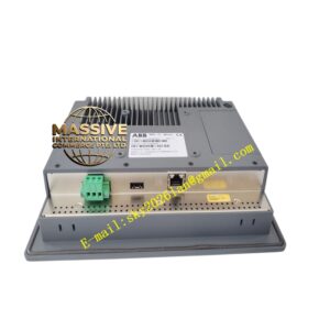
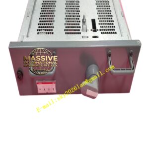
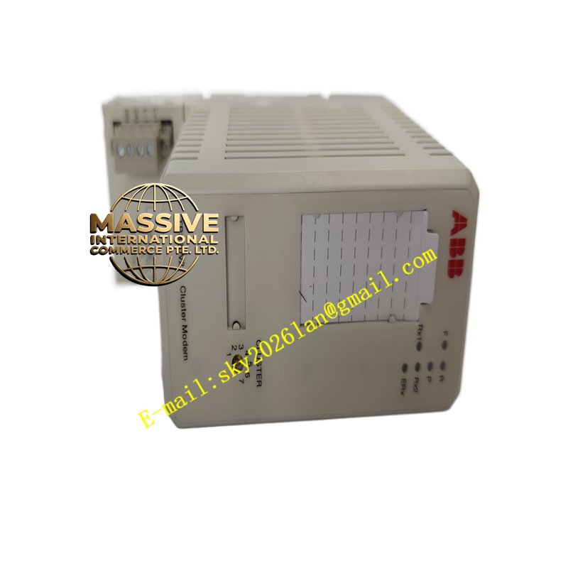
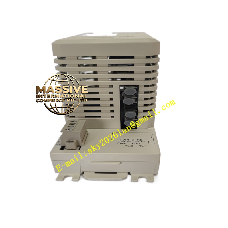
ABB TB820V2
- Technical Specifications:
- Compatible CPUs: PM865, PM866, PM876, PM891 (PM510/PM150 NOT compatible — they use BC810 single baseplate)
- Compatible PSUs: SD822 (24 V DC 5 A), SD823 (24 V DC 10 A), SD831 (redundant kit)
- CEX-Bus Slot: 1 (occupied by CEX option card — e.g., CI854A Profibus DP, CI840A S800 I/O IF)
- ModuleBus: 1 × 40-pin header — connects to TB521/TB511 S800 I/O rack via TK801V006 flat cable (max 12 modules local; more with repeaters)
- Redundancy: 1:1 hot-standby; switchover < one scan on primary failure
- Power: 24 V DC input via two PSUs (diode-OR); typical total system draw ≤30 W (CPUs + CEX + local I/O)
- Dimensions: ≈285 mm (W) × 125 mm (H) × 180 mm (D) — occupies two standard module slots width in cabinet
- Mounting: 35 mm DIN rail (heavy-duty) or panel-mount via screws
- Operating Temp.: 0 °C to +60 °C
- Certifications: CE, UL, cUL, ATEX Zone 2, marine
- Functional Features / Application / Material / Structure / Working Principle / Installation / Precautions:
- Used in every redundant AC 800M node — two PM8xx CPUs + BC820V2 + two PSUs + CEX card
- After power-up: primary boots; standby syncs → SYNC LED green on standby CPU
- On primary failure → standby takes over bumplessly; alarm raised
- Local S800 I/O: connect TK801V006 from BC820 ModuleBus header → TB521 ModuleBus header → I/O scanned directly by CPUs (both see same image)
- Precaution:
- Both CPUs must be identical model & firmware version
- Both PSUs should be same type — sized for full load + margin (N+1 redundancy)
- Before removing active CPU → verify standby SYNC LED green & “Redundant State: Synced” in 800xA — removing active forces switchover
- Firmware version must match Control Builder M version — check compat matrix before upgrade
- Keep spare BC820V2 if critical — though failure rate extremely low; more common to spare CPUs/PSUs