Description
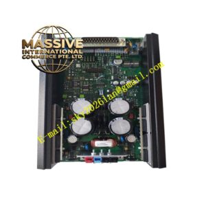
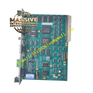
Alstom ALE111-S01
Technical Specifications Industrial-grade processing core; onboard non-volatile memory for logic program storage; rack backplane bus interface; 24V DC operating power supply; operating temperature range -20°C to +70°C; isolation voltage 1500V AC between internal logic circuit and field signal side; IP20 protection rating; built-in hardware watchdog circuit.
Functional Features Load and execute user-defined interlock and sequence control logic in fixed control cycles. Receive digital and analog process data from other I/O modules through the rack backplane bus. Output control instructions to related I/O modules to drive field auxiliary equipment. Conduct continuous hardware self-diagnosis for processor, memory and bus communication. Upload fault codes, equipment status and event records to the host monitoring system. Trigger pre-set safe state output when watchdog detects abnormal operation. Support online logic monitoring and parameter modification in engineering software.
Application Scenarios Thermal power unit auxiliary machine interlock control, hydropower unit auxiliary control, substation bay control cabinets, generator protection auxiliary logic processing, power plant boiler and turbine auxiliary control.
Performance Parameters Deterministic logic execution cycle with stable response time; high immunity to electromagnetic surge interference; long data retention of event logs after power loss; continuous stable operation under 24-hour unattended working mode.
Material Composition Main circuit PCB uses FR-4 flame-retardant multilayer printed circuit board; processor, memory and logic chips adopt wide-temperature industrial semiconductors; backplane gold finger contacts are gold-plated copper alloy; module outer housing uses flame-retardant thermoplastic resin; internal passive components are high stability industrial resistors and capacitors.
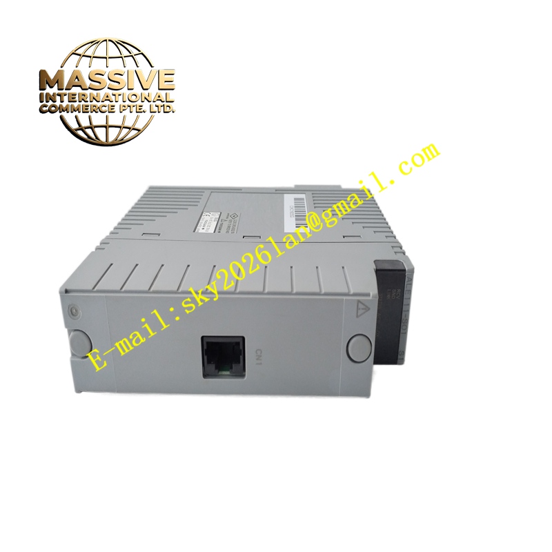
Structural Characteristics Vertical plug-in rack-mounted card form factor, compatible with standard Alstom control rack slots. Front panel integrates power, run, communication and fault LED indicator lamps. Rear gold finger connector realizes power supply and backplane bus data interaction. Side mechanical locking buckle fixes the module to prevent loosening under vibration.
Working Principle The module reads the pre-stored control logic program after power-on, and runs logic calculation in a fixed scanning cycle. It collects real-time signal status from other I/O modules via the backplane bus, completes condition judgment, and sends control commands to corresponding output modules. The self-diagnosis circuit monitors hardware status all the time, and records fault events into non-volatile storage when abnormality occurs.
Installation Requirements Cut off the power supply of the entire control rack before inserting or removing the module. Align the module with the rack guide rail and push it in place until the side buckle locks tightly. Configure rack address and communication parameters in supporting engineering software. Download control logic program and verify data interaction with all associated I/O modules. Complete interlock function test before the system is put into service.
Precautions for Use Take anti-static measures when touching exposed circuit boards. Keep the ventilation gap of the cabinet unblocked to ensure heat dissipation. Save complete backup files of logic programs and parameter settings. Do not hot swap the module when the rack is powered on.