Description
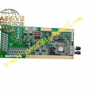
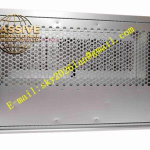
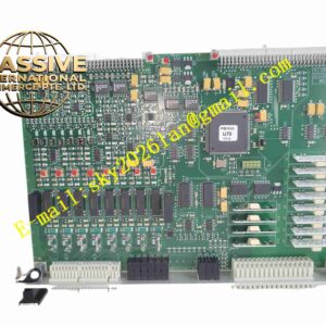
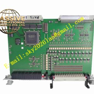
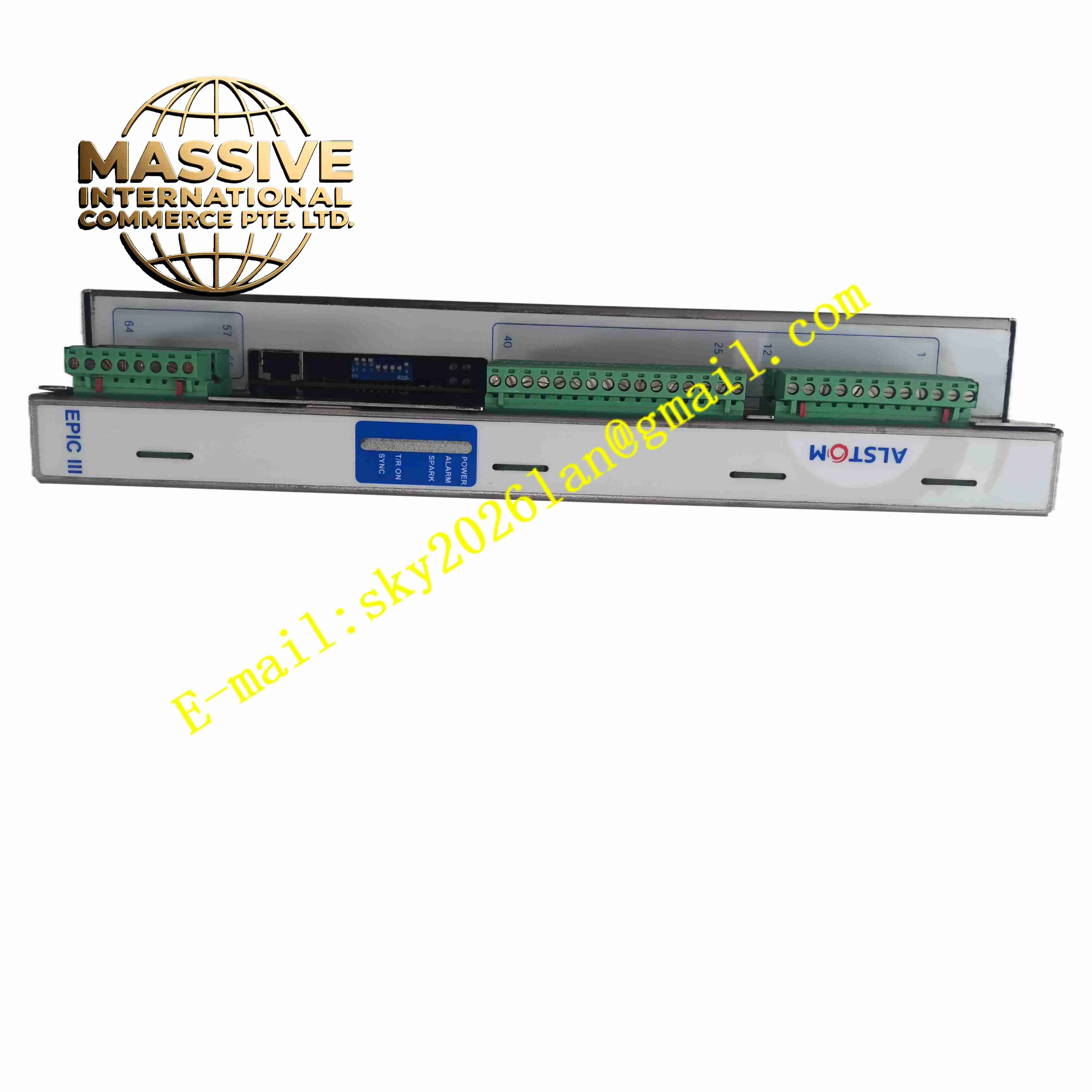
ALSTOM EP3-E-4-A
Technical Specifications:
- Power Supply: 220 VAC / 380 VAC wide input option
- Control Output: High frequency trigger signal for ESP high voltage rectifier transformer
- Communication: RS485 Modbus RTU interface for DCS connection
- Operating Temperature: -20 °C to +60 °C
- Storage Temperature: -40 °C to +85 °C
- Spark Detection Response Time: <1 ms
- I/O Channels: Multi-channel digital input and relay alarm output
- Enclosure: Cabinet panel mount, IP54 front panel rating
Function Features:
- Real-time spark detection and automatic spark quenching control
- Dynamic voltage and current regulation to maximize dust collection efficiency
- Multiple operation modes for different flue gas dust load conditions
- Continuous monitoring of ESP electrode and power supply status
- Alarm and fault relay output for flashover, overcurrent and power failure
- Historical event and spark frequency data logging
- Parameter setting and local status display via front HMI
- Data transmission to plant DCS system through Modbus bus
Application Scenarios:
- Coal-fired power plant electrostatic precipitator high voltage control
- Steel plant flue gas dust removal ESP systems
- Cement plant exhaust gas electrostatic precipitation equipment
- Waste incineration plant flue gas treatment
- Industrial boiler flue gas dust collection control systems
Material Composition:
- Front Panel: Flame retardant black plastic with display and keypad
- Main Enclosure: Painted steel sheet metal cabinet
- Main PCB: Multilayer FR4 printed circuit board with conformal coating
- Power Components: High voltage pulse drive chips, isolated signal transformers
- Relays: Industrial relay modules for alarm and fault output
- Terminals: Heavy duty screw terminals for power, I/O and communication wiring
Structural Features:
- Panel mounting rectangular cabinet design
- Front panel with LCD display and membrane operation keypad
- Internal separated low voltage control area and high voltage signal area
- Internal metal shielding to suppress high frequency electromagnetic interference
- Rear terminal blocks for field wiring connection
- Cabinet sealing gasket to prevent dust ingress
Working Principle: The controller samples high voltage and high current signals from ESP rectifier transformer. Internal circuit detects spark and flashover events in precipitator chamber. When spark occurs, controller immediately cuts off high voltage output and recovers power automatically after quenching. It adjusts high voltage amplitude and pulse frequency continuously according to dust concentration and spark frequency. Operation data and fault alarm information are transmitted to plant DCS via Modbus communication bus.
Installation Requirements:
- Install controller panel on ESP high voltage control cabinet
- Separate high voltage power cables from low voltage signal and communication cables
- Use shielded twisted pair cable for Modbus communication wiring
- Implement reliable protective earth connection for cabinet and shielding
- Keep cabinet sealed to prevent flue gas dust entering internal circuit
- Maintain cabinet ventilation and cooling
Usage Notes:
- Set spark threshold, recovery time and voltage limit parameters before commissioning
- High voltage hazard exists, cut off all high voltage and control power before maintenance
- Check cabinet sealing gasket regularly to avoid dust accumulation on PCB
- Backup controller parameter configuration after tuning
- Verify alarm relay action during plant outage test
- Avoid operating controller beyond rated voltage and current range