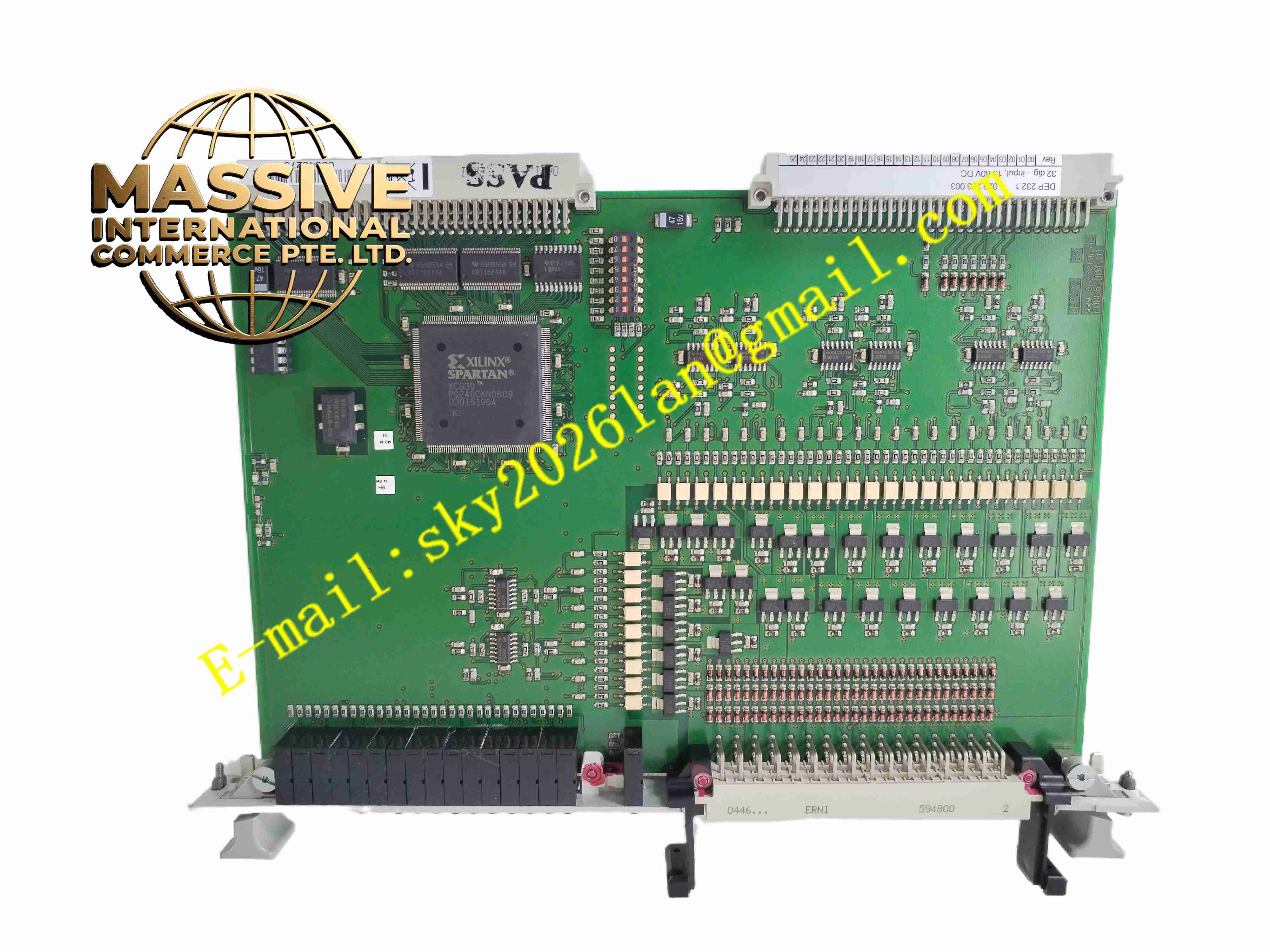
Description
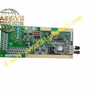
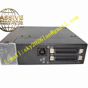
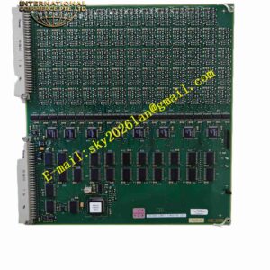
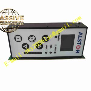
ALSTOM DEP232 029.223003
Technical Specifications:
- Signal Input: Multi-channel analog voltage and current signal sampling
- Power Supply: 24VDC internal cabinet power supply
- Output: Analog control signal to drive power stage
- Sampling Precision: High precision analog signal conversion
- Operating Temperature: -10℃ ~ +60℃
- Storage Temperature: -40℃ ~ +85℃
- Humidity: 5%~90% non-condensing
Function Features:
- Generator voltage and current signal acquisition and conditioning
- Excitation closed-loop control calculation
- Overexcitation, underexcitation and V/Hz protection logic
- Analog control output for power amplifier stage
- Internal self-test and fault signal alarm output
- Hardwired relay alarm contact for fault notification
Application Scenarios:
- Large thermal power generator excitation cabinets
- Hydropower station excitation control systems
- ALSTOM legacy excitation system maintenance and spare part replacement
Material Composition:
- Substrate: Multilayer FR4 fiberglass PCB
- Components: Precision operational amplifiers, ADC chips, logic ICs, capacitors and resistors
- Connectors: Gold-plated pin board-to-board connectors
Structural Features:
- Standard plug-in card structure for rack chassis installation
- Front panel with fault and running status LED indicators
- Edge connector for signal and power connection with backplane
- Metal shielding cover for anti-electromagnetic interference
Working Principle: The board receives analog voltage and current signals from PT and CT. Signal conditioning circuit processes raw signals, then analog-to-digital conversion sends data to control logic circuit. Control algorithm calculates required excitation control signal and sends analog command to power amplifier unit. Protection logic continuously monitors operating parameters and triggers alarm when abnormal condition occurs.
Installation Requirements:
- Insert into standard rack chassis of excitation cabinet
- Ensure clean backplane connector before insertion
- Maintain cabinet air conditioning to control temperature
- Keep away from high voltage and high magnetic field components
- Ensure reliable cabinet protective grounding
Usage Notes:
- Static protection must be applied during handling and installation
- Do not touch gold-plated connector pins directly
- Check connector tightness after card insertion
- Replace card only after cabinet power cut off
- Prevent dust accumulation on PCB surface