Description
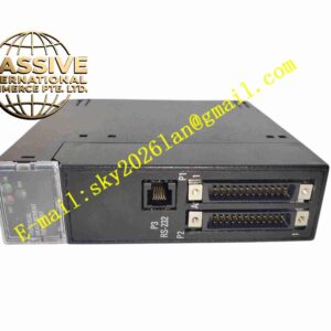
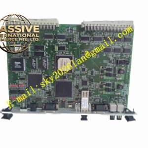
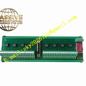
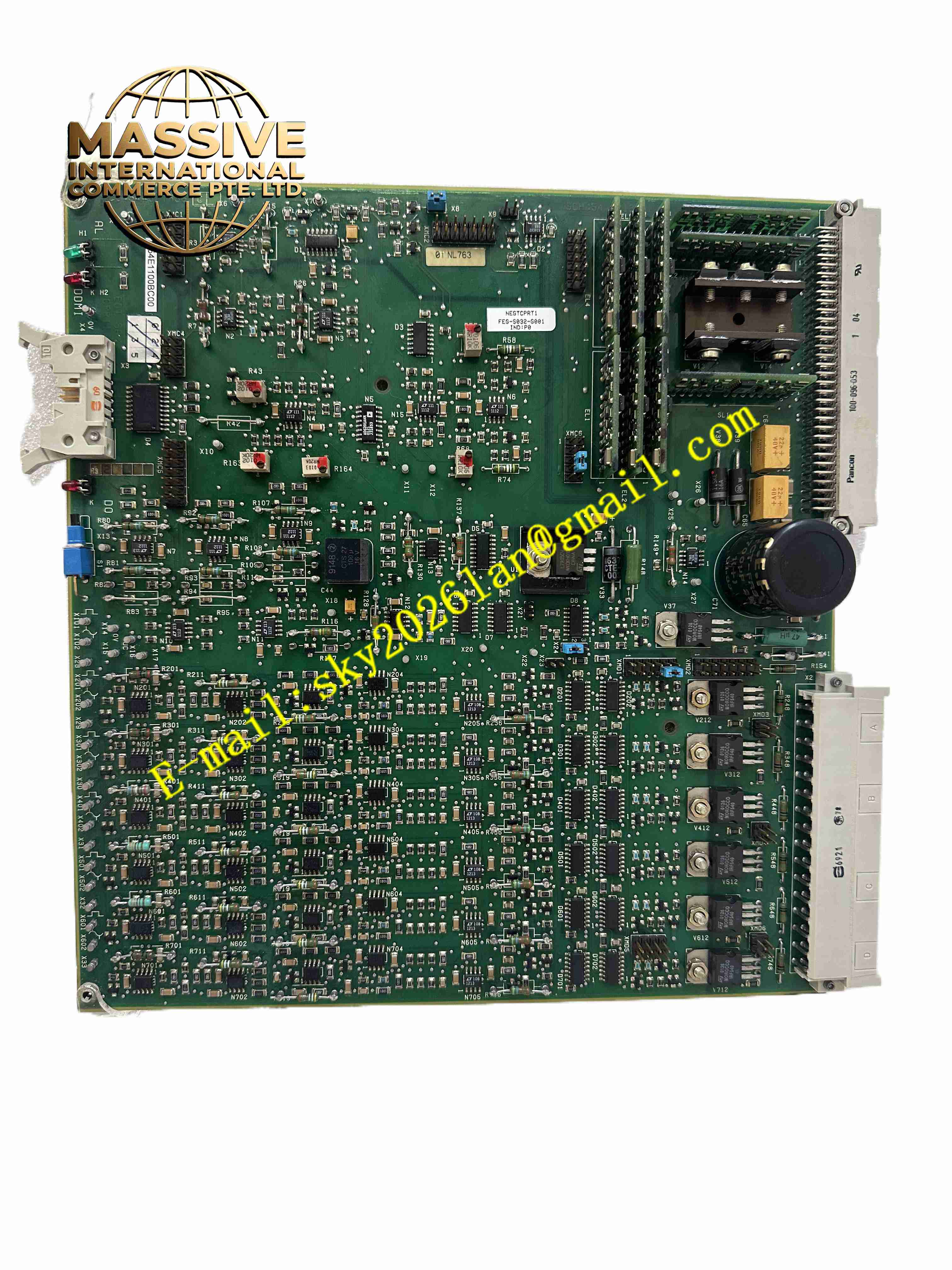
ALSTOM L54E1100BC00
Technical Specifications
- Board type: Protection device communication expansion
- Interfaces: Ethernet, RS485/RS232
- Protocol: IEC60870-5-103, Modbus
- Supply: Device internal DC5V
- Isolation: Communication port isolated from device internals
- Temperature: -10 °C to +55 °C
- Storage: -25 °C to +70 °C
- Humidity: 5 % to 95 %, non-condensing
- Protection: IP20
- Installation: Internal plug-in
- LEDs: Link, Act, fault
Functional Features
- Ethernet and dual serial communication
- IEC60870-5-103 protection standard
- Modbus RTU communication
- Communication port isolated from device internals
- On-board LEDs for network status
- Uploads protection operations, measurements, fault records
- Receives remote setting changes and remote commands
- Board-to-protection CPU internal bus communication
- Industrial-grade components
- Substation electromagnetic environment
Application Scenarios
- Alstom protection device communication expansion
- Substation integrated automation telecontrol
- Plant protection device background networking
- Substation IEC60870-5-103 network access
- Protection information substation access
Materials and Construction
- PCB: FR4 board
- Communication: Ethernet PHY, isolation transformer, serial transceivers
- Connector: Device board-to-board
- LEDs: SMD indicators
- Passive components: Resistors, capacitors
- Interfaces: RJ45, DB9 terminals
Structural Features
- Small PCB inserted into protection device expansion slot
- Front panel RJ45 and DB9
- On-board LEDs
- Board-to-board connector to protection CPU
- No independent housing, inside device
- Compact
Working Principle The board communicates with the protection CPU over a board-to-board connector, reads protection operations, measurements, and fault records, and packages them as IEC60870-5-103 or Modbus frames sent via Ethernet or serial to substation background and telecontrol. Setting changes and remote commands from background are parsed by the board and sent to the CPU. LEDs indicate communication.
Installation Requirements
- With device power off, open panel and insert expansion slot
- Connect network and communication wires to external terminals
- Use shielded twisted pair Ethernet
- Device grounding
- Temperature -10 °C to +55 °C
- Configure communication parameters in device menu after power-up
Precautions
- Install/remove board only with device power off
- Communication address and baud rate per substation design
- Firmly latch RJ45
- Store spares in anti-static packaging
- On communication faults check protocol and wiring
- Periodically back up protection settings