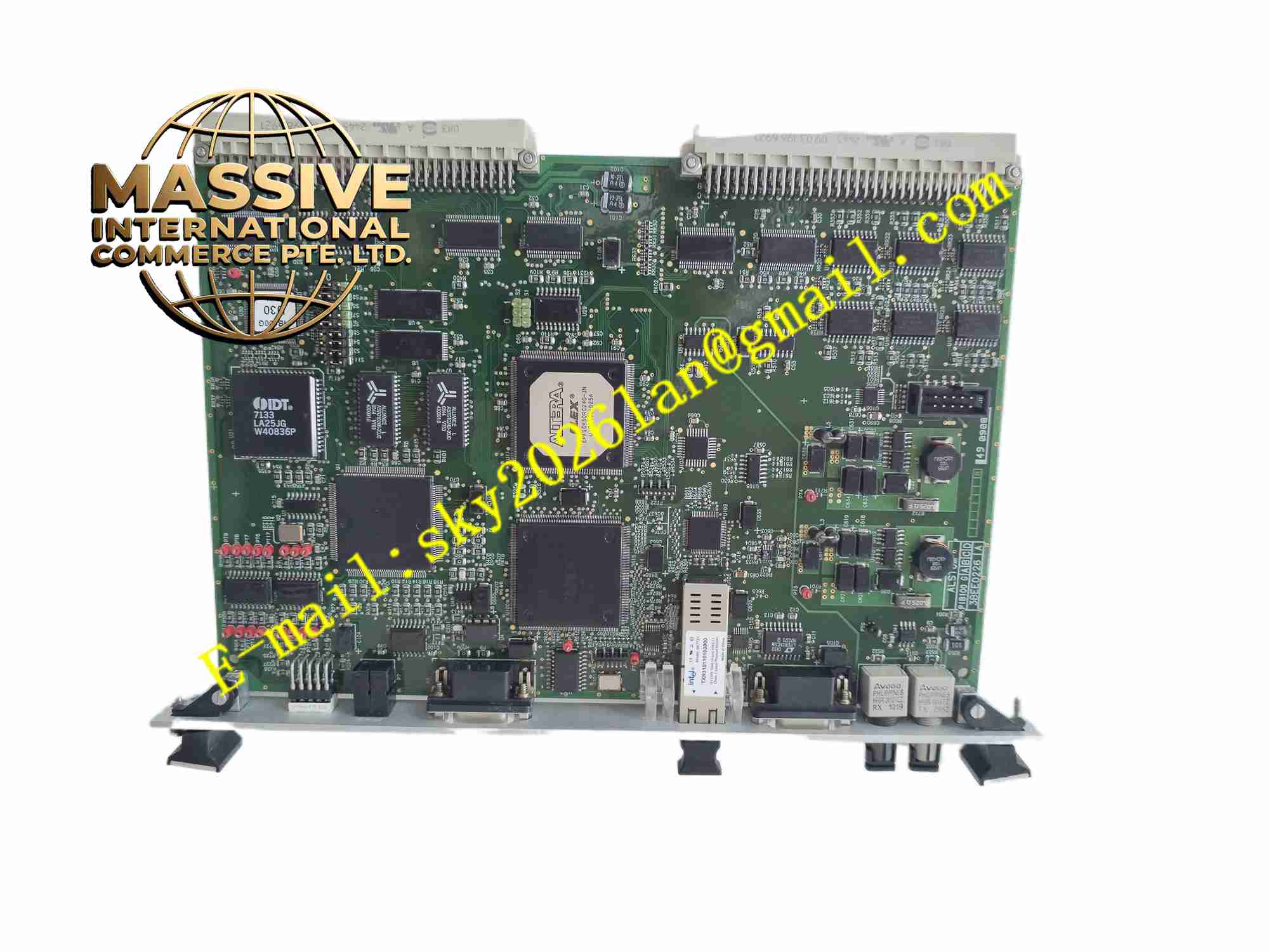
Description
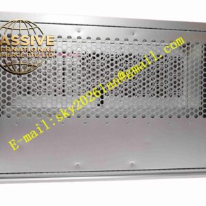
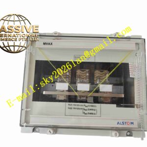
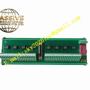
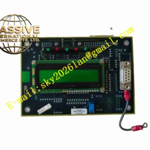
Alstom PIB100G 3BEE0226
Technical Specifications
- Product type: Process interface board
- Analog inputs: PT 100 V, CT 5 A
- Digital inputs: DC24 V
- Digital outputs: Relay contacts
- Isolation: 2500 VAC
- Supply: Device internal DC5 V
- Operating temperature: -10 °C to +55 °C
- Storage temperature: -25 °C to +70 °C
- Humidity: 5 % to 95 %, non-condensing
- Protection: IP20
- Installation: Plug-in
- Contact rating: AC250 V 5 A
Functional Features
- PT/CT AC signal isolated input
- Digital input/output isolation
- 2500 VAC electrical isolation
- Front panel LEDs per channel
- On-board TVS surge protection
- Board-to-board communication with protection CPU
- Industrial-grade components
- Substation electromagnetic environment
- Modular plug-in
- Long-term reliability
Application Scenarios
- Alstom protection device process interface
- Substation PT/CT signal access
- Power plant switch interface
- Electrical protection and measurement boards
- Substation integrated automation
Materials and Construction
- PCB: FR4 board
- Transformers: Miniature PT/CT
- Isolation: Optocouplers
- Connectors: Board-to-board and terminals
- Passive components: Resistors, capacitors, TVS
- Front panel: Metal panel
Structural Features
- Card structure in protection device slot
- Front panel PT/CT/DI/DO terminals
- Internal transformer, optocoupler, filter partitions
- Board-to-board connector
- Card locking mechanism
- Metal shielding
Working Principle PT/CT signals pass miniature transformers for isolation and scaling, then filter and connect to the protection CPU. Switch signals are opto-isolated and uploaded to CPU. CPU outputs drive optocouplers and relay contacts to the field. TVS absorbs surge. LEDs indicate channels.
Installation Requirements
- Insert device slot with power off
- Connect PT/CT secondary wires by phase
- CT secondary must not open-circuit
- PT secondary must not short-circuit
- Grounding
- Temperature -10 °C to +55 °C
- Verify ratio after power-up
- Correct switch signal polarity
Precautions
- CT secondary circuit must never open
- PT secondary circuit must never short
- Disconnect PT/CT before card insertion
- Ratio matches parameters
- Store spares in anti-static moisture-proof packaging
- Periodically calibrate sampling