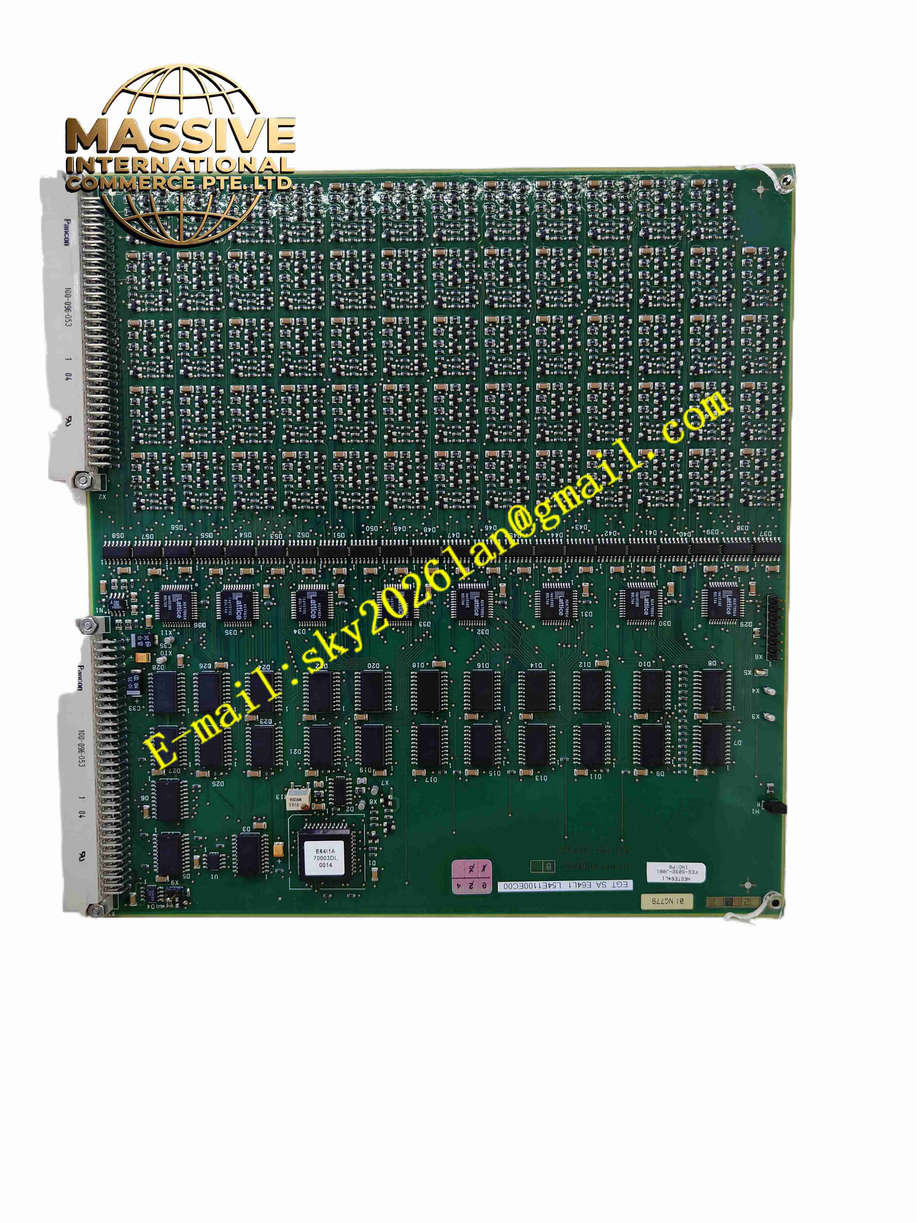
Description
ALSTOM L54E1100EC00
Technical Specifications
- Board type: Protection device serial communication
- Interfaces: RS485/RS232
- Protocol: Modbus RTU, IEC60870-5-103
- Supply: Device internal DC5V
- Isolation: Communication port isolated
- Baud rate: 300 to 19200 bps
- Temperature: -10 °C to +55 °C
- Storage: -25 °C to +70 °C
- Humidity: 5 % to 95 %, non-condensing
- Protection: IP20
- Installation: Internal plug-in
- LEDs: Communication, fault
Functional Features
- RS485/RS232 serial communication
- Modbus RTU and IEC60870-5-103
- Communication port isolated
- Uploads protection measurements and event records
- Receives remote commands
- On-board LEDs for communication
- Configurable baud rate
- Industrial-grade components
- Substation EMI environment
- Internal bus communication with CPU
Application Scenarios
- Alstom protection device serial expansion
- Substation Modbus RTU access
- Plant protection device telecontrol serial
- Power protection information acquisition
- Substation integrated automation serial networking
Materials and Construction
- PCB: FR4 board
- Communication: RS485/RS232 isolated transceivers
- Connector: Board-to-board
- LEDs: SMD indicators
- Passive components: Resistors, capacitors
- Interface: DB9 or terminals
Structural Features
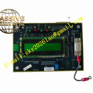
- Small PCB in protection device expansion slot
- Front panel DB9 or terminals
- On-board LEDs
- Board-to-board connector to CPU
- No independent housing
- Compact
Working Principle The board exchanges data with the protection CPU over a board-to-board connector, packages measurements and events as Modbus RTU or IEC60870-5-103 frames sent via RS485/RS232 to substation background. Commands from background are parsed to the CPU. LEDs indicate transmit/receive.
Installation Requirements
- Insert expansion slot with device power off
- Shielded twisted pair communication wire
- 120 Ω termination at RS485 bus end
- Device grounding
- Temperature -10 °C to +55 °C
- Set baud rate and address after power-up
Precautions
- Install/remove board only with power off
- RS485 A/B polarity must not be reversed
- Same baud rate both ends
- Store spares in anti-static packaging
- On communication faults check termination
- Periodically back up settings