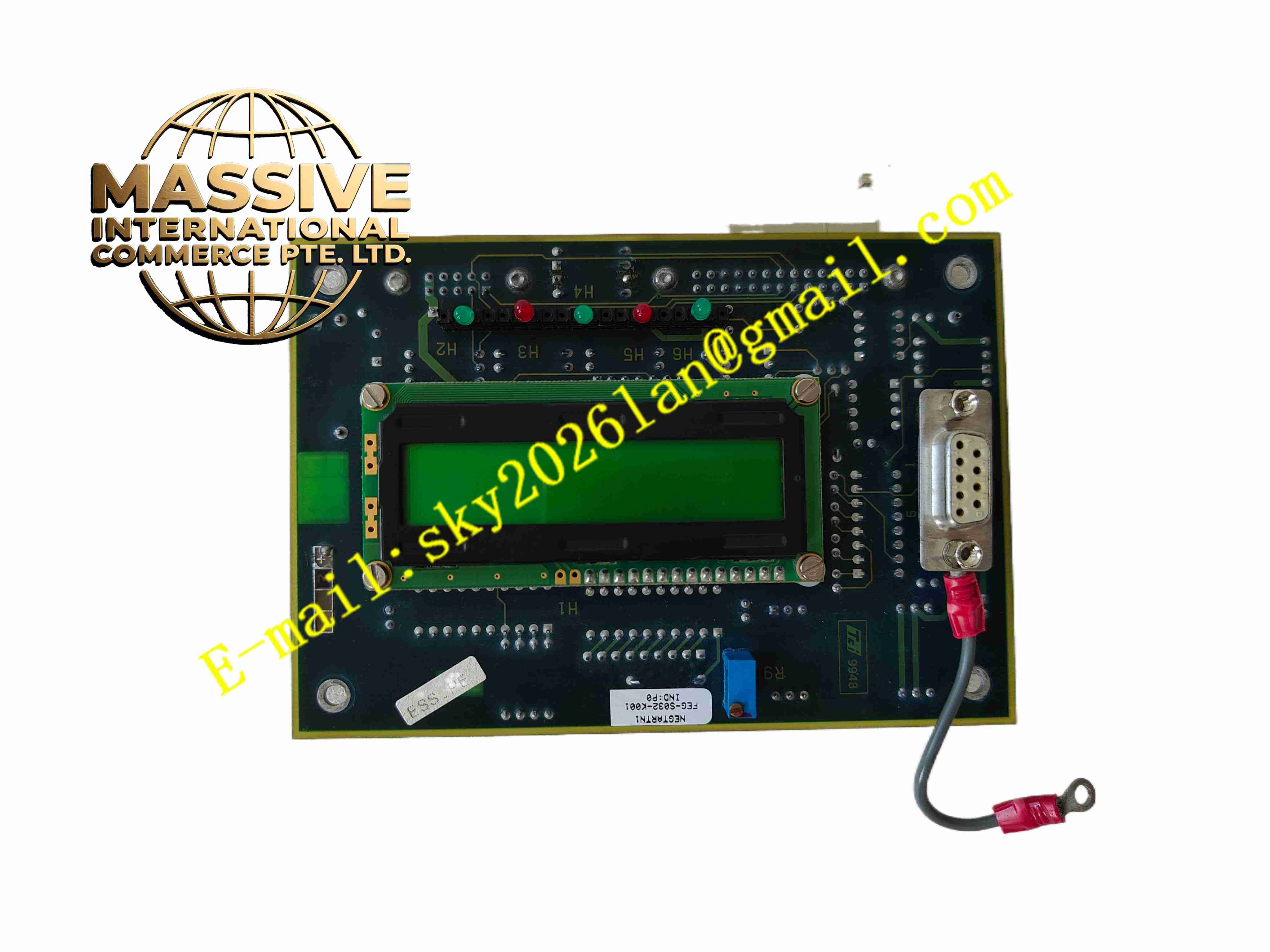
Description
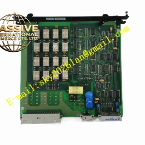
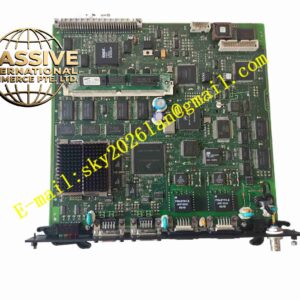
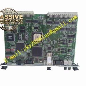
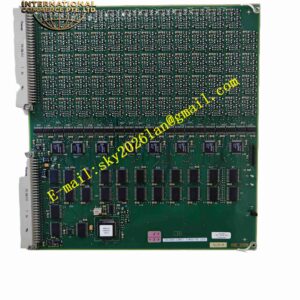
ALSTOM L54E2901TW00
Technical Specifications
- Board type: AC analog input board
- Inputs: PT 100 V, CT 5 A/1 A
- Channels: Multi voltage and current channels
- Sampling: AC sampling
- A/D resolution: 16 bits
- Accuracy: 0.2 class
- Supply: Device internal DC5V
- Isolation: PT/CT input isolated from board
- Temperature: -10 °C to +55 °C
- Storage: -25 °C to +70 °C
- Humidity: 5 % to 95 %, non-condensing
- Protection: IP20
- Installation: Internal plug-in
Functional Features
- PT secondary voltage and CT secondary current sampling
- 16-bit high-resolution A/D
- 0.2 class measurement accuracy
- Independent isolation of voltage and current circuits
- On-board anti-aliasing filters
- Sampled data uploaded to protection CPU over internal bus
- Supports measurement, protection, and metering accuracy
- On-board overvoltage protection with PT/CT surge absorption
- Industrial-grade components
- Substation strong EMI environment
Application Scenarios
- Alstom line protection device AC sampling
- Transformer protection voltage/current acquisition
- Motor protection and measurement device analog input
- Substation integrated automation AC sampling
- Plant auxiliary power protection device sampling
Materials and Construction
- PCB: FR4 board
- Sampling: Miniature PT/CT, A/D chip
- Passive components: Metal film resistors, capacitors, TVS
- Connector: Board-to-board
- Terminals: Screw-fastened terminals
Structural Features
- Small PCB in protection device analog input slot
- Front panel PT/CT wiring terminals
- On-board miniature instrument transformers and sampling
- Anti-aliasing filter at input stage
- Board-to-board connector to CPU
- No independent housing
Working Principle PT secondary voltage and CT secondary current enter terminals; miniature voltage and current instrument transformers isolate and scale signals, which after conditioning and anti-aliasing filtering are sampled by 16-bit A/D to digital. The protection CPU reads samples over the internal bus and calculates voltage, current, power, and frequency for protection algorithms and metering. On-board TVS absorbs loop surge.
Installation Requirements
- Insert analog slot with device power off
- Connect PT/CT secondary wires per drawing
- CT secondary must not open-circuit
- PT secondary must not short-circuit
- Device grounding
- Temperature -10 °C to +55 °C
- Verify ratio setting after power-up
Precautions
- CT secondary circuit must never open
- PT secondary circuit must never short
- Disconnect PT/CT before inserting board
- Ratio matches device parameters
- Store spares in moisture-proof packaging
- Periodically calibrate sampling accuracy