Description
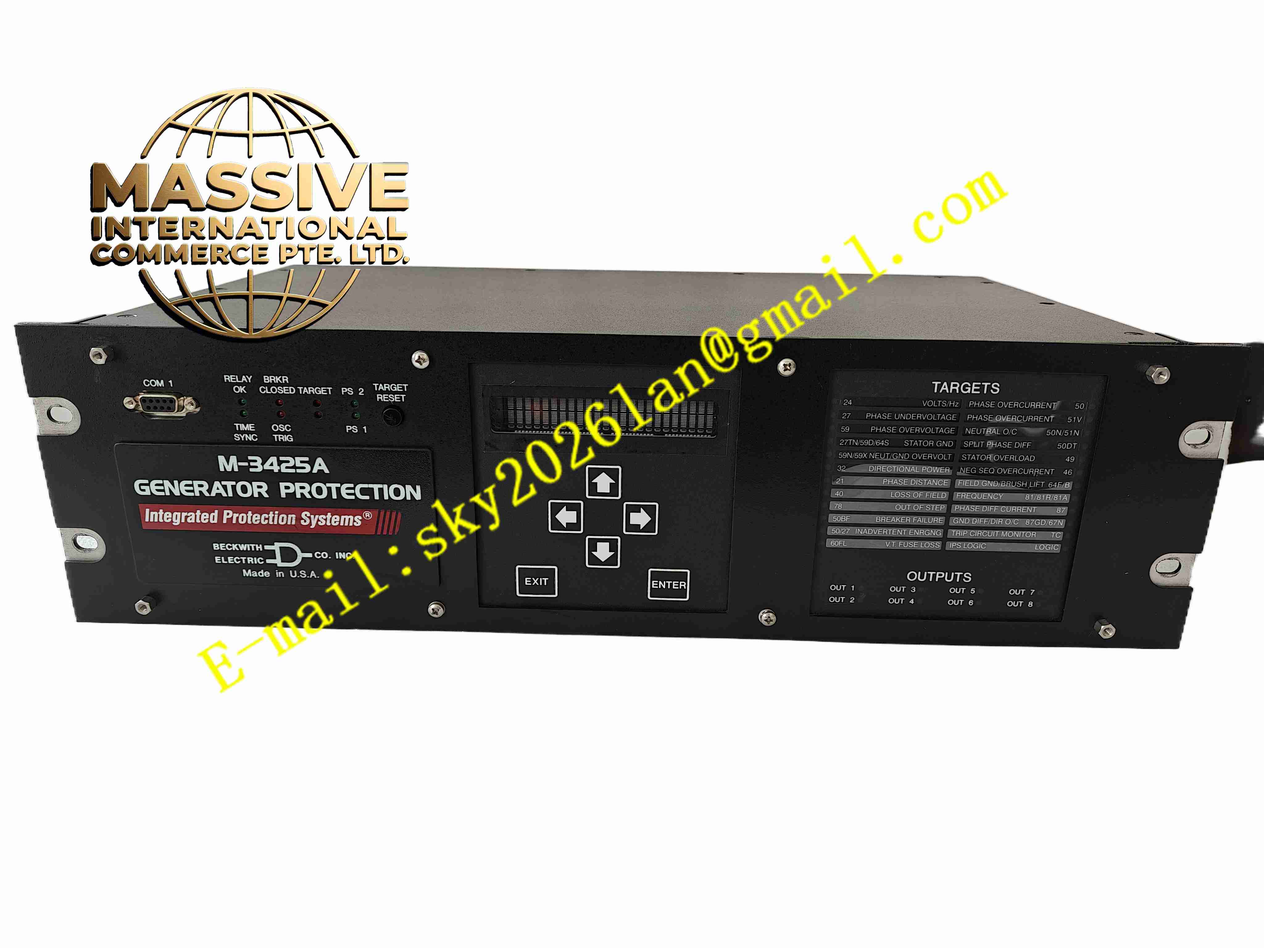
Beckwith Electric M-3425A
Technical Specifications 3-phase voltage input 100V to 480V AC; CT secondary current input 1A or 5A; Measurement accuracy ±0.5%; 8 programmable digital inputs; 8 programmable relay outputs; Power supply 24V-250V DC or 120V-240V AC; RS232, RS485, optional Ethernet communication.
Functional Features Overexcitation V/Hz protection; Reverse power protection; Negative sequence overcurrent protection; Phase differential protection; Under/over voltage protection; Under/over frequency protection; Thermal overload protection for stator and rotor; COMTRADE oscillographic fault recording; Time stamped event log; Programmable logic; Synchronism check function.
Application Scenarios Thermal power station generator protection; Hydroelectric generator set control; Industrial on-site backup generator; Distributed energy generator protection; Combined cycle power generation unit.
Performance Parameters Operating ambient temperature -30℃ to +70℃; Storage temperature -40℃ to +85℃; Relative humidity 5% to 95%, no condensation; Complies with IEEE C37.90, IEC 60255 protection relay standards.
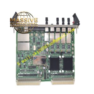
Material Composition Metal rack mount housing; Multi-layer high precision measurement PCB; High-speed analog sampling circuit; Embedded microprocessor chip; Backlit LCD display; Electromechanical output relays; Nickel-plated screw terminals.
Structural Characteristics 19-inch rack mount enclosure; Front panel with LCD screen, operation keypad and LED target indicators; Rear terminal block for CT, PT and control wiring; Internal separation of high voltage measurement circuit and low voltage digital processing circuit.
Working Principle Current transformer and voltage transformer analog signals enter the relay. High-speed sampling circuit converts analog signals into digital values. Embedded processor runs multiple protection algorithms simultaneously. When measured values cross protection pickup thresholds, relay contacts operate to trip generator circuit breaker. All fault waveforms and event records store in non-volatile memory.
Installation Requirements Mount unit in relay cabinet on standard 19-inch rack. Connect CT and PT secondary wiring strictly following schematic. Wire trip and alarm output circuits. Configure protection setting values via front keypad or configuration software. Perform protection function simulation test after commissioning. Ensure cabinet protective earthing.
Usage Notes Do not short circuit CT secondary terminals when live. Backup protection setting files before firmware upgrade. Inspect relay contact wear periodically. Keep cabinet dust-free and well ventilated. Calibrate measurement circuit according to power plant maintenance schedule.