Description
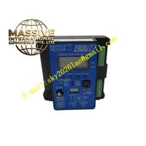
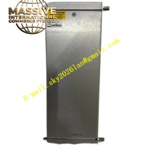
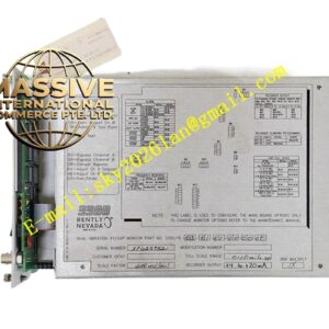
Bently 3500/53‑02‑00 (133396‑01)
- Key Features: Four independent pulse‑input channels; supports magnetic‑pickup and proximity‑probe pulse‑signal sources; measures rotational‑speed, overspeed detection, reverse‑rotation identification and acceleration‑rate monitoring; per‑channel configurable Alert and Danger alarm thresholds; supports redundant speed‑input voting‑logic; hot‑swap maintainability; front‑panel multi‑color LED status indicators.
- Technical Specifications & Performance Parameters
- Input channel quantity: 4 independent pulse‑input channels
- Maximum measurable rotational speed: 200 000 RPM
- Typical power consumption: 7.0 W
- Operating temperature: 0 ℃ ~ +60 ℃
- Storage temperature: ‑40 ℃ ~ +85 ℃
- Weight: 0.47 kg
- Material Composition: FR‑4 multilayer high‑speed signal printed circuit board; high‑speed pulse‑capture FPGA chip; signal‑conditioning and surge‑suppression circuit components; gold‑plated back‑plane edge connector; metal front‑panel with LED status indicators; metal shielding housing for high‑speed pulse‑signal circuits; mechanical locking latch assembly.
- Structural Features: Full‑height plug‑in rack‑module mechanical construction; front‑panel LED indicators for power‑supply, channel‑signal presence and alarm‑status; rear‑side gold‑plated edge connector connects to rack‑back‑plane bus; field‑sensor wiring terminates on matched corresponding I/O termination module; mechanical locking latch secures module position inside rack slot.
- Working Principle: Field‑mounted pulse‑transducer generates pulse‑trigger signal corresponding to shaft rotational movement. Pulse‑signal transmits to speed‑monitor module via I/O termination assembly. Internal high‑speed FPGA circuit captures pulse‑edge events, counts pulse frequency and computes real‑time shaft rotational‑speed, rotation‑direction and acceleration‑rate values. Calculated values compare with user‑programmed alarm setpoints. Alarm‑status flags transmit over rack‑back‑plane bus to relay‑output modules and communication‑gateway modules.
- Application Scenarios: Overspeed‑protection monitoring for steam‑turbine, gas‑turbine and centrifugal‑compressor units; reverse‑rotation detection for large rotating‑machinery; shaft‑speed measurement for generator sets; multi‑transducer redundant speed‑voting‑logic implementation in SIL‑capable turbomachinery‑protection systems; petrochemical and power‑plant critical‑equipment TSI racks.
- Installation Requirements: Insert full‑height speed‑monitor module into designated rack slot; lock mechanical latch firmly; install matched I/O termination module for field‑pulse‑sensor wiring; configure pulse‑per‑revolution value, alarm thresholds and voting‑logic rules through 3500 rack‑configuration software; perform barring‑shaft test to verify real‑time speed reading correctness after commissioning.
- Usage Notes: Apply ESD static‑protection measures during module handling; avoid unauthorized hot‑swap operation without following official maintenance workflow; inspect front‑panel channel‑signal LED status during daily inspection; back‑up complete rack‑configuration‑file after adjusting speed‑protection‑related parameters; check pulse‑sensor wiring tightness during equipment overhaul cycles.