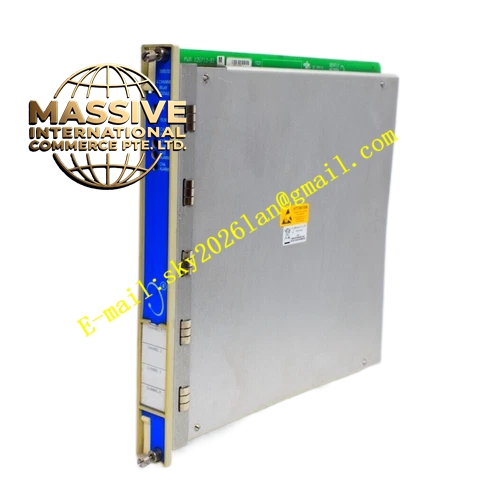
Description
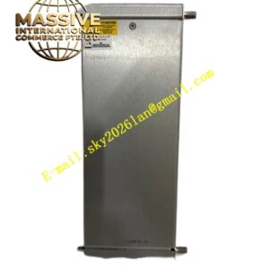
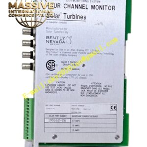
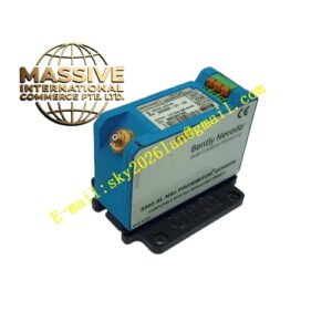
Bently Nevada 3300/40
Technical Specifications
| Parameter | Specification |
|---|---|
| Input | Two proximity probe signals |
| Input Impedance | 10 kΩ |
| Scale Factor | 7.87 V/mm (200 mV/mil) on AISI 4140 steel target at 1.0 mm gap |
| Field Wiring | 0.2–1.5 mm² (16–24 AWG), maximum length 305 m |
| Recorder Output | 4–20 mA or 0 to -10 Vdc |
| Alarm Relays | Dual relay alarm options (non-epoxy sealed) |
| Operating Temperature | 0°C to +65°C |
| Dimensions | 241.3 mm × 114.3 mm × 25.4 mm |
| Weight | Approximately 0.45 kg |
| Origin | USA |
Functional Features
- Measures peak-to-peak shaft eccentricity during slow-roll conditions
- Uses dual proximity probes for accurate bow detection
- Provides early warning of shaft bow, misalignment, and foundation problems
- Offers real-time recorder outputs for trending and analysis
- Features dual relay alarm outputs for proactive maintenance
- Includes front-panel display for direct eccentricity reading
- Performs continuous transducer OK checking
- Supports programmable alarm setpoints
Structural Characteristics The eccentricity monitor is constructed as a standard 3300 rack module with a front panel containing an LCD bargraph display, LED indicators, and programming switches. The unit accepts inputs from two proximity probes mounted 90 degrees apart around the shaft circumference. The internal signal processing circuitry extracts the slow-varying DC component representing shaft bow from the dynamic vibration signal.
Working Principle During slow-roll operation (typically 100–500 RPM), two proximity probes mounted orthogonally on the bearing housing measure the distance to the shaft surface. As a bowed shaft rotates, the probe-to-shaft distance varies sinusoidally at the rotational frequency. The monitor extracts this slow-roll variation, filters out higher-frequency vibration components, and measures the peak-to-peak amplitude. This value represents the total indicated runout (TIR) or eccentricity of the shaft. The monitor compares this value against alarm thresholds to warn operators of excessive bow before attempting full-speed operation.
Installation Requirements
- Install two proximity probes at 90-degree offset positions around the shaft
- Mount probes at identical radial distances from the shaft centerline
- Use shielded coaxial cable for all transducer connections
- Ensure proper probe gap setting for linear range operation
- Program alarm setpoints based on manufacturer slow-roll limits
- Verify eccentricity measurement during known slow-roll conditions
- Test alarm relay operation before placing in service
Application Scenarios
- Large steam turbine slow-roll monitoring
- Generator shaft bow detection
- Compressor startup eccentricity measurement
- Motor rotor bend assessment
- Refinery critical equipment startup supervision
- Power plant turbine supervisory instrumentation