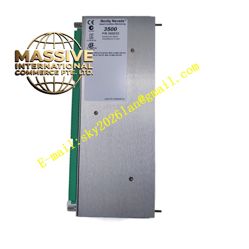
Description
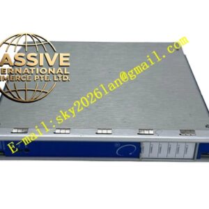
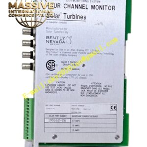
Bently Nevada 3300/50-01-02-01-01
Technical Specifications
- Full-Scale Range: Standard speed range
- Transducer Input: 100 mV/mil sensitivity compatible input
- Signal Types: TTL, magnetic pickup sensors, eddy-current proximity probes
- Frequency Range: 0 to 10 kHz
- Input Voltage Range: 0.5 V to 50 V peak-to-peak
- Speed Measurement Range: 1 to 99,999 rpm
- Acceleration/Deceleration Range: -9,999 to +9,999 rpm per minute
- Accuracy: ±1 rpm for speed, ±20 rpm per minute for acceleration
- Response Time: Less than 1 ms for real-time monitoring
- Alarm Relays: Epoxy-sealed SPDT contacts
- Recorder Output: Programmable +4 to +20 mA, 0 to -10 Vdc, or +1 to +5 Vdc
- Power Supply: 24 Vdc rack power
- Operating Temperature: -20°C to +65°C
- Storage Temperature: -40°C to +85°C
- Humidity: Up to 95% non-condensing
Functional Features
- Continuous rotational speed measurement
- Zero-speed detection capability
- Rotor acceleration and deceleration tracking
- Peak speed memory function for post-event analysis
- Programmable alarm setpoints for overspeed and underspeed
- Epoxy-sealed relays for environmental protection
- Buffered transducer outputs on coaxial connectors
- CSA/NRTL/C certified for applicable hazardous locations
Application Scenarios
- Turbine speed monitoring and protection
- Compressor and pump rotational surveillance
- Motor overspeed detection
- Gearbox and coupling speed ratio verification
- Process control systems requiring speed feedback
- Emergency trip system integration
Performance Parameters
- High-resolution speed counting across entire range
- Stable frequency tracking with fluctuating amplitudes
- Fast alarm response preventing catastrophic overspeed events
- Low power consumption for continuous operation
- Accurate acceleration calculation for trend analysis
Material Composition
- Enclosure: Industrial-grade metal or composite housing
- Front panel: Durable polymer or anodized aluminum
- Circuit assemblies: Conformal coated for moisture resistance
- Relays: Epoxy-sealed for contamination protection
- Connectors: Nickel or gold-plated for signal integrity
Structural Characteristics
- Compact module design for 3300 rack installation
- Front panel digital display for local speed indication
- Coaxial connectors for buffered signal access
- Terminal strips for power and relay connections
- Standard card retention with rack mounting hardware
Working Principle The monitor receives pulse signals from a magnetic pickup or proximity probe sensing a gear tooth or keyphasor slot. An internal frequency-to-voltage converter transforms the pulse repetition rate into a DC voltage proportional to rotational speed. This voltage drives the front panel meter, the recorder output, and the alarm comparators. Acceleration is derived by differentiating the speed signal over time. Alarm circuits continuously compare speed and acceleration against setpoints to trigger relay actions.
Installation Requirements
- Mount in a standard 3300 series monitor rack
- Magnetic pickups require specific distance from ferrous targets
- Proximity probes must be gapped within their linear range
- Shielded cable must be used for transducer connections
- Relay contacts require appropriate snubbing for inductive loads
Usage Precautions
- Verify pickup polarity when using magnetic sensors
- Set overspeed alarm thresholds with adequate safety margin above normal operating speed
- Test zero-speed functionality during commissioning
- Do not exceed the maximum input voltage on the transducer channel
- Periodic verification of speed calibration against a reference standard is recommended