Description
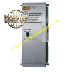
Bently Nevada 3500/53-03-03-00
Technical Specifications
- Product Type: Electronic Overspeed Detection System
- Channels: Three-channel configuration
- Signal Input: Proximity probes or magnetic pickups, +10 V to -24 V range, 20 kΩ input impedance
- Frequency Response: 1 to 255 events per revolution
- Maximum Full-Scale RPM: 99,999 rpm
- RPM Accuracy: ±0.1 rpm below 100 rpm, ±1 rpm from 100 to 10,000 rpm, ±0.01% above 10,000 rpm
- Recorder Output: +4 to +20 mA with 100 ms update rate
- Relay Type: SPDT epoxy-sealed, 5 A maximum switching current
- Power Consumption: 8.0 watts typical
- Operating Temperature: -30°C to +65°C
- Storage Temperature: -40°C to +85°C
- Humidity: 95% non-condensing
Functional Features
- Configurable 2-out-of-2 or 2-out-of-3 voting logic for redundant protection
- Automatic and manual transducer threshold configuration
- Adjustable hysteresis from 0.2 V to 2.5 V
- Fast alarm response time under 30 ms for inputs above 300 Hz
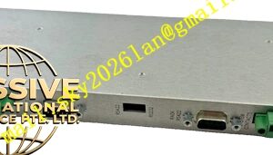
- Buffered transducer outputs via front panel coaxial connectors
- Front panel LEDs indicating OK, TX/RX, Bypass, Test, and Alarm states
- Recorder output for continuous speed logging
Application Scenarios
- Steam and gas turbine overspeed protection
- Compressor and pump speed monitoring
- Generator and motor rotational safety systems
- High-speed industrial machinery protection
- Emergency shutdown system integration
Performance Parameters
- High-resolution speed measurement across entire range
- Stable frequency detection even with fluctuating signal amplitudes
- Relay contact life rated for 100,000 operations at 5 A
- Low power consumption relative to channel count
- Immunity to electrical noise in industrial environments
Material Composition
- Enclosure: Industrial metal housing with protective coating
- Circuit boards: Epoxy-glass laminate with conformal coating
- Connectors: Nickel or gold-plated brass
- Relays: Epoxy-sealed contacts for environmental protection
Structural Characteristics
- Standard 3500 series monitor module dimensions
- Front panel BNC connectors for buffered outputs
- Rack-compatible card edge with locking tab
- Status LED array for rapid diagnostic assessment
- Separate I/O module for field wiring termination
Working Principle The monitor receives pulse signals from a proximity probe or magnetic pickup mounted adjacent to a toothed wheel or keyphasor mark on the rotating shaft. An internal comparator converts the analog pulses into digital events. A precision timer measures the interval between successive pulses to calculate instantaneous rotational speed. This calculated speed is compared against user-defined overspeed setpoints. Upon detection of an overspeed condition, the module energizes or de-energizes relay contacts to initiate a machine trip sequence.
Installation Requirements
- Requires installation in a 3500 rack with redundant power supplies
- Must be paired with the appropriate I/O module for signal termination
- Proximity probes require proper gap adjustment to ensure reliable pulse detection
- Magnetic pickups must be installed at the manufacturer-recommended distance from the target
- Voting configurations require inter-module communication links to be properly established
Usage Precautions
- Redundant power supplies are mandatory for all racks hosting overspeed detection modules
- Verify pulse signal quality at the I/O module before enabling speed alarms
- Test overspeed trip logic regularly using the built-in test function
- Do not bypass voting logic during normal operation
- Maintain firmware at the revision level specified for the application