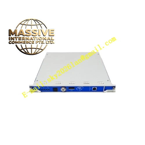
Description
Bently Nevada 991-06-50-01-00
Technical Specifications
- Base Model: 991 Thrust Transmitter
- Full-Scale Range: 0 to 6 mils (0 to 150 µm) or -0.6 to +0.6 mm depending on configuration
- System Length: 5.0 meters (16.4 feet)
- Mounting Option: 35 mm DIN-rail clips
- Agency Approval: Not required
- Power Supply: +12 to +35 Vdc loop-powered
- Output Signal: 4 to 20 mA proportional to axial displacement
- Accuracy: Within ±1.5% of full-scale range
- Maximum Loop Resistance: 1,000 Ω at 35 Vdc
- Current Limiting: 23 mA typical
- Zero and Span: Non-interacting external adjustments
- Not OK/Signal Defeat: Output drops to less than 3.6 mA within 100 µs after a Not OK condition
- Recovery Time: Restores within 0.1 seconds after condition resolution
- Operating Temperature: -35°C to +85°C
- Storage Temperature: -51°C to +100°C
- Humidity: 0 to 100% RH non-condensing
Functional Features
- Integrated Proximitor sensor eliminates need for external signal conditioning unit
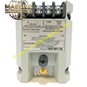
- Non-isolated PROX OUT and COM terminals plus coaxial connector provide dynamic gap voltage signal for diagnostics
- Non-interacting zero and span potentiometers allow field calibration without cross-effects
- Test input pin enables quick loop verification using a variable DC voltage source
- Power-up inhibit circuit prevents false signal errors during power line transients
- Signal defeat circuit inhibits high outputs or false alarms from faulty probes or loose connections
- Potted construction designed for environments with up to 100% condensing humidity
Application Scenarios
- Centrifugal air compressor thrust bearing monitoring
- Small pump axial position measurement
- Electric motor rotor thrust surveillance
- Fan thrust load assessment
- General rotating machinery axial displacement monitoring requiring 4-20 mA output
Performance Parameters
- Sensitivity: 0.0001 mm/V
- Linearity: ±0.02% of full scale
- Response Time: Less than 100 µs for fault detection
- Output Stability: Maintained over full operating temperature range
- Probe Gap Target: -10 Vdc for optimal linear operation
Material Composition
- Housing: Industrial-grade aluminum or coated metal
- Internal Circuitry: Epoxy-potted for moisture and vibration resistance
- Connectors: Gold-plated brass for signal integrity
- Probe Tip: Polyphenylene sulfide
- Probe Case: AISI 304 stainless steel
Structural Characteristics
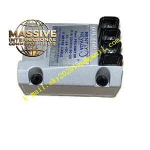
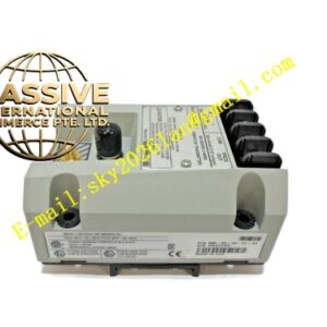
- Compact DIN-rail mountable enclosure
- Front-facing terminal blocks for power and signal connections
- Coaxial connector for diagnostic equipment interface
- Sealed potting compound filling internal cavity
- Spring-loaded DIN-rail retention clips
Working Principle The transmitter drives a 3300 NSv proximity probe with high-frequency RF energy. The probe tip generates an alternating electromagnetic field that induces eddy currents in the metal target surface. As the target moves axially, the energy loss in the target changes the probe coil impedance. The transmitter detects this impedance change, demodulates it, and converts the displacement information into a proportional 4-20 mA current signal that flows in the two-wire power loop.
Installation Requirements
- Mount on standard 35 mm DIN-rail in a vibration-free control enclosure
- Connect loop power supply with proper polarity
- Ensure total loop resistance does not exceed 1,000 Ω at 35 Vdc
- Set probe initial gap to achieve approximately -10 Vdc at center of linear range
- Use shielded cable for 4-20 mA signal with shield grounded at control system end
Usage Precautions
- Verify power supply voltage is within +12 to +35 Vdc range before connection
- Do not use grounded AC-powered test equipment on PROX OUT without 122115-01 isolation adapter
- Adjust zero and span using insulated screwdriver to prevent short circuits
- Monitor output current during commissioning to verify proper probe gap setting
- Replace probe if output remains below 3.6 mA indicating Not OK condition