Description
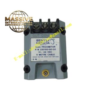
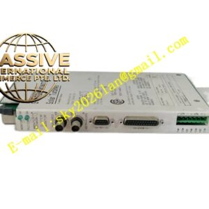
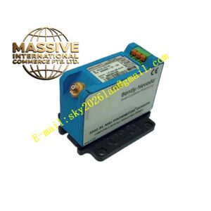
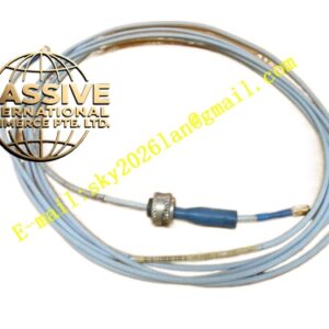
Bently Nevada ANA-D3510-100-A1 120M8155-01
Technical Specifications Multi-channel signal input for proximity probes and velocity transducers; supports 4-20mA analog output; built-in transducer power supply; 24V DC module auxiliary power supply; signal bandwidth covers low-frequency vibration and shaft displacement measurement; operating temperature -20°C to +70°C; IP20 protection rating; internal circuit galvanic isolation between sensor field wiring and control system side.
Functional Features Supply regulated excitation power to field proximity probes and vibration velocity sensors. Condition raw transducer signals including filtering and amplitude scaling. Convert displacement and vibration measurements into standard 4-20mA analog signals for host control systems. Detect sensor open-circuit, short-circuit and power supply faults and generate alarm status. Transmit real-time measurement values and diagnostic status over system backplane bus. Support sensor linearization and measurement range configuration through supporting software.
Application Scenarios Turbine shaft vibration monitoring, centrifugal compressor shaft displacement measurement, large industrial pump machinery protection, generator rotating component condition monitoring, high-speed rotating machinery online health monitoring.
Performance Parameters Low signal noise amplification; high linearity across full measurement range; stable gain under long-duration continuous operation; fast sensor fault identification speed.
Material Composition Main PCB uses FR-4 flame-retardant multilayer printed circuit board; precision signal processing and isolation components include optocouplers and instrumentation amplifiers; backplane gold finger contacts are gold-plated copper alloy; module outer housing is flame-retardant thermoplastic resin; terminal contact springs use nickel-plated copper alloy.
Structural Characteristics Plug-in rack module designed for Bently Nevada standard monitoring racks. Front panel carries LED indicators for power, communication and channel fault status. Rear gold finger connector connects to rack backplane for bus communication and module power supply. Front screw terminal blocks accept field transducer wiring. Side mechanical latches lock the module to resist cabinet vibration.
Working Principle Field proximity probe or velocity sensor signals enter the module signal conditioning circuit after receiving excitation power from the module. High-frequency noise superimposed on raw signals is filtered out. Processed signals are scaled according to configured measurement range and converted into 4-20mA analog output. Onboard diagnostic circuits continuously monitor sensor loop integrity and upload measurement and fault data to the rack host controller.
Installation Requirements Cut off rack auxiliary power before module installation or replacement. Insert the module into the designated rack slot and lock the side latches. Run shielded twisted-pair cables between field transducers and module input terminals. Set transducer type and measurement range in supporting configuration software. Conduct loop calibration and sensor fault simulation test after power restoration.
Precautions for Use Route sensor shielded cables separately from high-current power cables. Implement single-point grounding for cable shielding layers. Do not apply voltage exceeding transducer excitation rating to input terminals. Take anti-static protective measures when handling modules outside the rack.