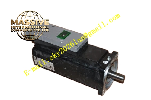
Description
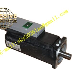
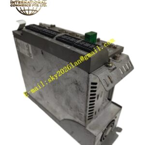
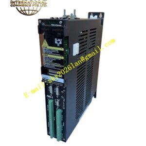
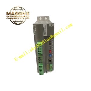
ELAU ISH070‑60017‑0‑1‑00‑0‑10‑00‑00
Technical Specifications Flange Dimension: 70 mm square mounting flange Rated Speed: 6000 rpm Rated Torque: 1.7 Nm Rated Voltage: 400 V AC class Encoder Type: Resolver analog feedback Built‑in Component: DC24V spring‑actuated power‑off holding brake Shaft Configuration: Flat‑key output shaft Connector Type: 90‑degree rotatable circular power and feedback connectors Protection Class: IP65 Operating Ambient Temperature: ‑20℃ to +60℃ Storage Temperature: ‑25℃ to +70℃ Cooling Method: Natural convection cooling Mounting Type: Flange face mounting
Functional Features Resolver feedback structure realizes reliable position and speed signal output under strong vibration and wide‑temperature industrial conditions. Built‑in spring‑type power‑off holding brake locks output shaft mechanically after brake coil power loss for vertical‑load position retention. Brake releases shaft rotation freedom upon DC24V excitation voltage input. Embedded electronic motor nameplate supports automatic motor parameter identification by matched servo drive. 90‑degree rotatable circular connectors adjust cable outlet orientation for compact machine internal wiring layout. F‑grade stator winding insulation maintains stable thermal performance under long‑time cyclic working condition. IP65‑rated housing resists dust, oil mist and partial liquid splashing contamination. Internal NTC temperature sensor monitors winding real‑time temperature state.
Application Scenarios Vertical motion axes of packaging machinery operating under harsh vibration environment; lifting‑lowering mechanisms of converting equipment; servo axes inside high‑temperature workshop automated production lines.
Performance Parameters Steady‑state speed control accuracy reaches ±0.01%. Short‑term overload capability achieves 250% of rated torque. Resolver signal requires homing sequence execution at every machine power‑on cycle to establish absolute position reference. Built‑in holding brake outputs stable static holding torque for static load locking. Overall motor axial length increases due to internal brake assembly.
Material Composition Die‑cast aluminum alloy motor housing, silicon‑steel laminated stator core, neodymium‑iron‑boron permanent magnet rotor assembly, resolver analog feedback assembly, electromagnetic brake friction plate subassembly, fluorine rubber sealing gaskets, alloy‑steel flat‑key output shaft, metal rotatable circular connector assemblies, built‑in NTC temperature sensing devices.
Structural Characteristics 70‑mm square mounting flange with flat‑key machined output shaft. Rear‑end dual rotatable circular connectors separate power circuit and resolver‑brake signal circuit. Internal brake assembly occupies extra axial space to lengthen overall motor body dimension. Metal housing nameplate prints complete part number ISH070‑60017‑0‑1‑00‑0‑10‑00‑00. Resolver sensing components are installed on rotor rear shaft end position.
Working Principle Upper‑level servo drive outputs three‑phase variable‑frequency alternating current to stator windings and generates rotating magnetic field to drive permanent‑magnet rotor rotation. Resolver analog sensing assembly collects rotor angular position and rotational speed signals and transmits analog feedback signals to servo controller for closed‑loop motion calculation. When DC24V brake power supply cuts off, brake spring pushes friction plates to lock motor shaft for static holding. When DC24V excitation voltage energizes brake coil, friction plates separate and shaft obtains free rotation status. NTC sensor continuously sends winding temperature data to upper‑level drive unit.
Installation Requirements Tighten flange mounting screws strictly follow torque parameters printed on motor nameplate. Complete high‑precision coaxial alignment between motor output shaft and load coupling assembly. Deploy shielded power cables and shielded resolver‑brake composite signal cables, fully lock circular connectors after insertion. Separate low‑level analog signal wiring physically from high‑voltage power cables. Supply stable DC24V power source for brake coil circuit. Ensure reliable protective earth connection for motor housing.
Usage Notes Built‑in holding brake applies exclusively for static position retention after power‑off, dynamic braking during motor running operation is prohibited. Complete homing procedure after each machine power‑on cycle. Forbid striking or hammering motor output shaft surface. Wear anti‑static wrist strap during resolver related maintenance work. Protect circular connectors against oil contamination and moisture penetration. Keep housing heat dissipation slots unobstructed. Operate within defined ambient temperature operating range.