



Description
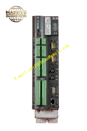
ELAU MAX‑4‑11‑03‑016‑08‑1‑0‑00
Technical Specifications CPU Core: Real‑time optimized industrial processor Program Memory: 16 MB Flash Data Working Memory: 8 MB RAM Maximum Controlled Axis Count: 8 axes Communication Interfaces: SERCOS fiber‑optic interface, Ethernet service port, RS232 serial port, RS485 interface On‑board Digital Inputs: 12 points On‑board Digital Outputs: 8 points Power Supply: DC24V, 1.4 A rated consumption Protection Class: IP20 Operating Ambient Temperature: 0℃ to +55℃ Storage Temperature: ‑25℃ to +70℃ Mounting Type: Standard DIN‑rail cabinet mounting
Functional Features Supports IEC‑61131‑3 standard logic control and hard‑real‑time multi‑axis motion calculation. Realizes electronic cam, electronic gear ratio, flying‑shear cutting and mark‑registration synchronization motion functions. SERCOS fiber‑optic communication achieves high anti‑interference performance and microsecond‑level inter‑axis synchronization. Non‑volatile flash memory preserves user application program, production recipe and configuration parameters after power‑loss. Built‑in diagnostic module records SERCOS bus faults, servo axis error codes and digital I/O status history. Ethernet interface completes program download, online debugging and equipment status monitoring. RS232 and RS485 serial ports support data interaction with peripheral auxiliary devices. Hardware watchdog circuit maintains system stable running status. Extended hardware safety function module is not equipped on this hardware variant.
Application Scenarios Medium‑size multi‑axis packaging machines; label automation production lines; secondary packaging handling equipment; converting machinery without high‑level hardware safety requirements.
Performance Parameters Minimum real‑time motion task cycle reaches 250 microseconds. Inter‑axis synchronization deviation stays below ±1 microsecond. Non‑volatile flash memory stores historical fault log records for post‑failure analysis. Deterministic execution timing keeps stable under full‑load 8‑axis operating condition.
Material Composition Aluminum alloy shielding housing, FR‑4 high‑speed multilayer printed circuit boards, industrial real‑time processor chip, fiber‑optic transceiver modules, flash memory chips, plug‑in screw‑lock terminal blocks, SMD LED status indicator components.
Structural Characteristics Vertical DIN‑rail compatible housing form factor. Front panel arranges LED status indicator array, Ethernet service port and RS232 serial connector. SERCOS fiber‑optic connection ports are located on upper housing edge. Pluggable terminal blocks for digital I/O channels and DC24V power‑supply input are arranged on lower housing section. Metal identification nameplate permanently prints complete part number MAX‑4‑11‑03‑016‑08‑1‑0‑00. Internal circuit omits corresponding extended safety hardware circuit components.
Working Principle User application program stored in internal flash memory executes on real‑time processor core. Logic processing section scans digital input signals and generates digital output actions following machine workflow sequence. Motion processing section calculates position command values for each servo axis, transmits command data frames over SERCOS fiber‑optic bus to connected servo drives and ISH integrated motors. Status and fault feedback data return from drive units back to MAX‑4 controller. Internal diagnostic modules continuously monitor hardware health, communication link quality and I/O channel integrity. Application program and configuration parameters keep retention inside non‑volatile flash memory after power‑off. Hardware watchdog executes automatic reset operation when abnormal program running status is detected.
Installation Requirements Mount controller onto standard DIN‑rail inside properly‑grounded industrial control cabinet. Preserve sufficient surrounding clearance for natural‑convection heat dissipation. Respect minimum‑bending‑radius constraints for SERCOS fiber‑optic cables. Physically separate low‑signal communication wiring from high‑voltage motor‑power cables. Apply DC24V control‑power‑supply with strict polarity compliance. Connect protective‑earth terminal to cabinet protective‑ground busbar.
Usage Notes Forbid hot‑plugging SERCOS fiber‑optic connectors under powered‑operating condition. Create full backup of user‑application program before firmware‑upgrade or hardware‑replacement work. Operate strictly within published ambient‑temperature operating‑range. Wear anti‑static wrist straps during internal circuit maintenance service. Avoid hardware exposure to conductive dust, heavy oil mist and corrosive industrial vapors.





