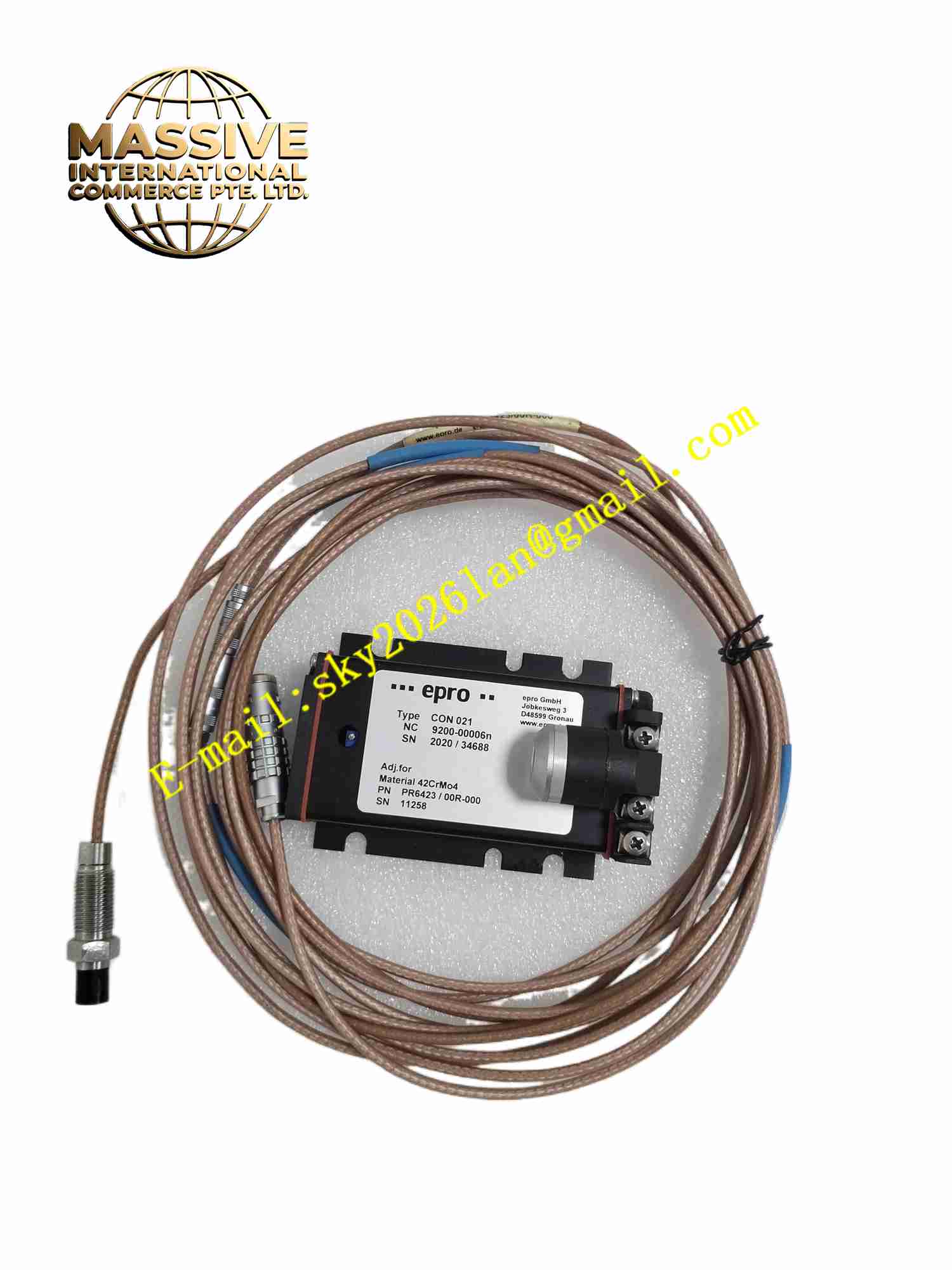
Description
EPRO PR642300R-000
Technical Specifications Model: PR642300R-000 Measurement Principle: Eddy current non-contact sensing Probe Body Material: Stainless steel with ceramic tip Operating Temperature: -35℃ ~ +180℃ Measuring Range: 0 ~ 2mm standard range Mounting Structure: External thread mounting Cable Type: Integrated shielded coaxial cable Protection Grade: IP67 Storage Temperature: -40℃ ~ +185℃ Relative Humidity: 5% ~ 95% non-condensing
Functional Features Non-contact measurement without mechanical friction and wear. High temperature resistant probe body suitable for installation near turbine and compressor bearing housings. Built-in high-frequency sensing coil encapsulated in ceramic insulation to resist vibration and temperature impact. Shielded coaxial cable reduces external electromagnetic interference. Compatible with EPRO series signal converters to convert gap value into standard analog signal. The probe can detect tiny gap variation caused by shaft vibration. Stable measurement performance on ferromagnetic metal shaft surface. Threaded structure allows precise adjustment of installation gap.
Application Scenarios Steam turbine shaft vibration monitoring, centrifugal compressor shaft displacement monitoring, large generator set condition monitoring, industrial gas turbine protection system, large circulating pump shaft vibration measurement.
Performance Parameters High linearity within the full measurement range. Micrometer-level displacement resolution for capturing small vibration amplitude. The coil and ceramic packaging maintain stable performance under long-term high temperature and vibration environment. Coaxial cable shielding suppresses electromagnetic interference from motor and power cable. Measurement linearity keeps stable after repeated temperature cycling. Threaded mounting structure maintains fixed gap after lock nut tightening.
Material Composition Probe shell: High strength stainless steel alloy. Sensing coil: High temperature enameled copper wire wound coil. Insulation encapsulation: High temperature resistant ceramic material. Probe cable: Fluorine plastic insulated shielded coaxial cable. Threaded fitting and lock nut: Stainless steel. Internal filling material: High temperature insulating sealant.
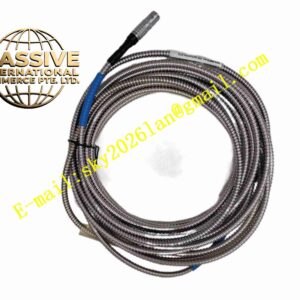
Structural Features Cylindrical probe body with external thread for installation on bearing housing. Front tip uses solid ceramic material to encapsulate sensing coil. Integrated shielded coaxial cable extends from rear of probe body. Threaded section with lock nut to fix probe after gap adjustment. Compact tip structure allows installation in limited space near bearing assembly.
Working Principle When matched signal converter sends high-frequency excitation current to probe internal coil, alternating magnetic field generates at probe tip. When metal shaft is placed near probe tip, eddy current forms on metal surface. Eddy current produces reverse magnetic field and changes coil impedance. The impedance value depends on the gap distance between probe tip and metal shaft. The signal converter detects coil impedance variation and converts gap distance into standard analog signal. The monitoring system collects analog signal and calculates shaft vibration amplitude and relative position.
Installation Requirements Drill and tap threaded hole on rotating machine bearing housing according to probe thread specification. Screw probe into threaded hole, adjust gap between probe tip and shaft into specified working range. Tighten lock nut to fix probe position after gap adjustment. Lay integrated coaxial cable inside protection conduit, avoid sharp bending and pulling force. Connect coaxial cable to matched EPRO signal converter terminal. Complete gap calibration with calibration target block before machine startup. Check no contact between probe tip and rotating shaft after installation.
Usage Precautions Probe tip collision with rotating shaft will permanently damage internal coil and ceramic encapsulation. Cable cannot bear heavy tensile load, avoid sharp bending smaller than minimum bending radius. Do not cut or splice integrated coaxial cable arbitrarily, which destroys measurement linearity. Regular visual inspection of probe and cable during equipment overhaul. Probe must be matched with corresponding EPRO signal converter, cannot work independently. Strong external magnetic field near probe installation point affects measurement accuracy.